I have an very odd power problem on my Ortur laser master 2 with Lightburn.
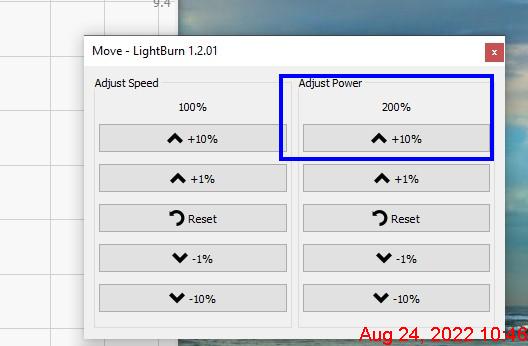
It seems like with a power setting of 100% I only get 50% form the laser output. However while etching I can increase the power by clicking on the power change up to 200% in the Move window which pops up while etching.
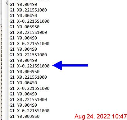
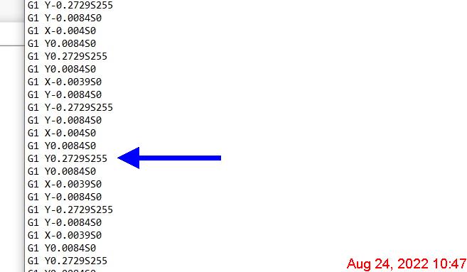
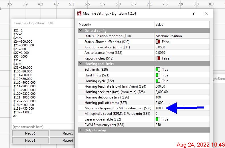
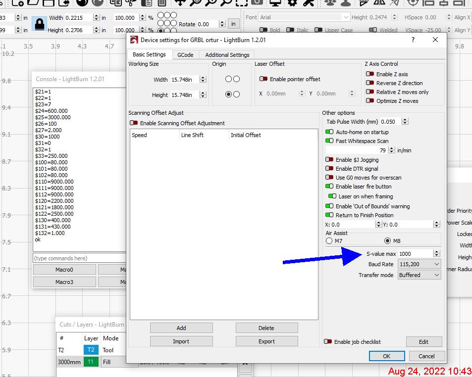
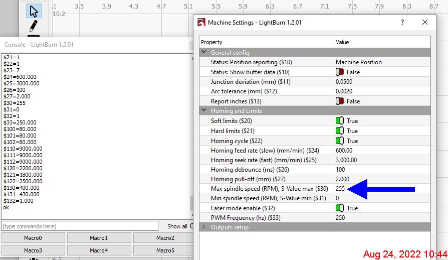
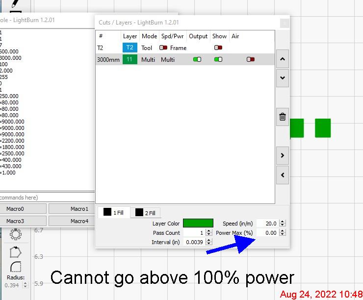
I have changed the setting in the 3 locations I know about that effect the power settings (setting, device, and machine/console pages). I first used $30= 255 then to $30=1000, this is also show in the G-code following in each change of the settings. In the selection for the power I can never go above 100% only changing it during the etch in the Move page.
The original setting were set on installation by going to fine my laser and it is shown as GRBLortur.
As stated I have tried both 255 and 1000 values in the different locations for power ratings, with no change. I am assuming 50% by the etching results. By increasing the % to 200% I get very good etching. This is not the correct way and should not be allowed, and I think shows the problem that something is wrong in the software. I did enter the correct value into the correct locations for the 2 different values, so don’t think I have them mixed. All 255 at one time and then all 1000 the next try same results not full power unless change while etching in the Move page manually to 200%.
If I’m reading the screenshots correctly it looks like things are working as expected. If you have $30=1000 and S Value Max set to 1000 and ask for 100% power you will get S1000 which is equivalent to 100% power. Similarly, if you have $30=255 and S Value Max set to 255 and ask for 100% power you will get S255 in your gcode.
From what I can tell the Adjust Power controls in Move window literally override max power and is handled within the controller. It’s not clear to me how it’s electronically implemented and it surprises me that you’re getting more output by doing this.
If you have a meter you should check PWM signal coming out of the controller for before you do this and after you do this.
You won’t be able to see the actual PWM signal with a meter. But to add to what @Colin indicated you can still measure voltages on the line. These lasers almost universally use TTL so is working with a 5V signal. Meters will “average out” the PWM TTL signal such that 0% power will be roughly 0V and 100% will be a full 5V in a linear fashion.
I suspect you’ll measure 5V at 100% coming out. I’m not sure what will happen when you override to 200% of that.
I did make a small jumper for the 3 wire connecter input for the laser module and attached a meter on the Black and white wires. I assume the Black to Red would indicate +12 volts and the Black to White would show the TTL voltage which was about 2.8 volts with slight a fluxation. With no real change with the 200% increase on the Move page.
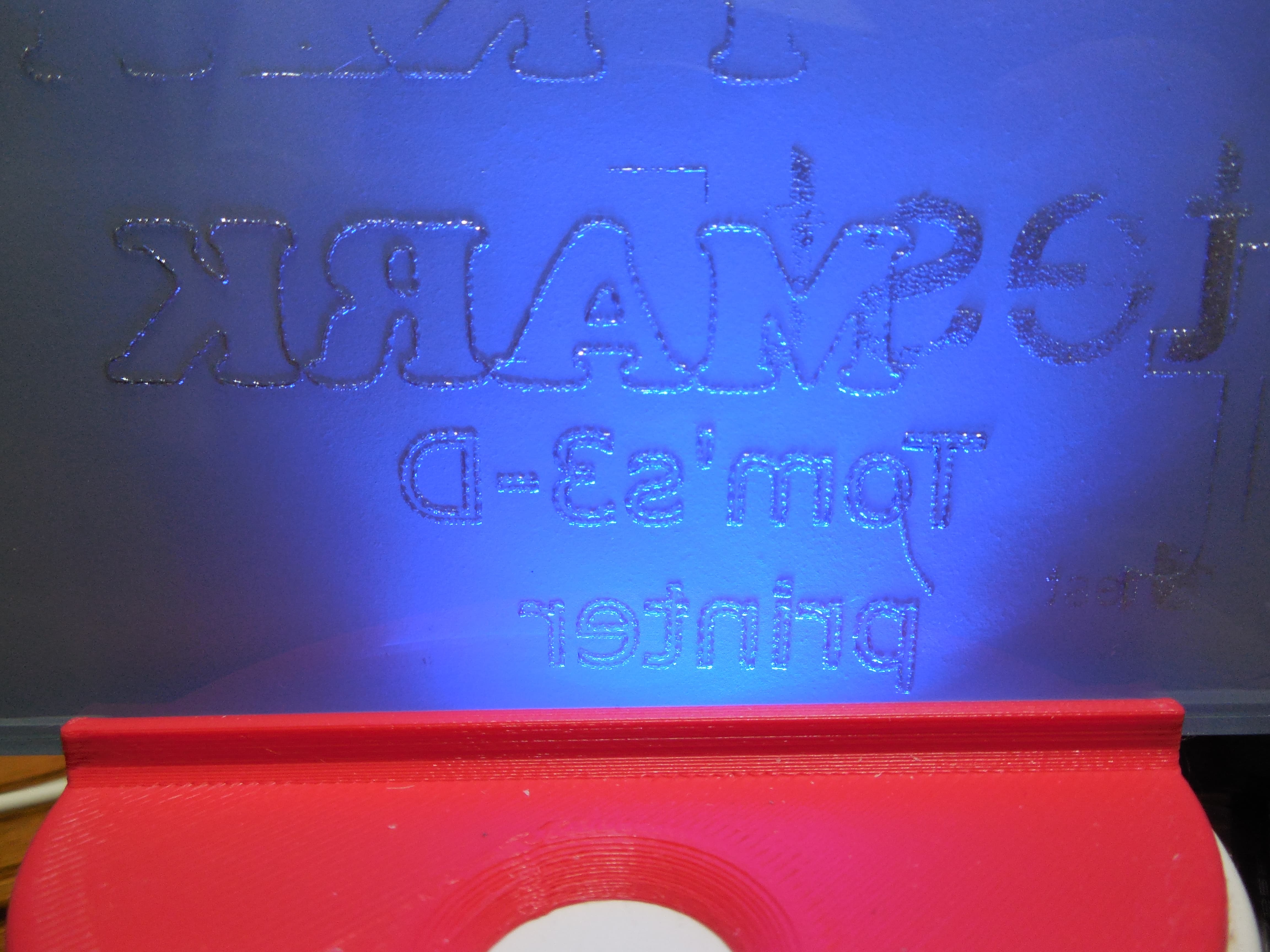
Ok I found if I use LaserGRBL on the same computer to control the laser I get a much better etch on the back of a glass tile. I had both lightburn and LaserGRBL using the 255 max power setting. I see it seems the LaserGRBL does give me a much better laser output. My next test will be going back to the earlier version of Lightburn will give me the results I had before. Not sure if I can get the earlier version as a download at this date.
the 2 attached image are of the Glass tile etch not pretty just a test, but with lightburn I could not etch through the backing coating on the tile. But I can with the LaserGRBL!!! Image using LED edge lighting forgot to reverse the etching but the results shows it can be done.
I did download an older version of Lightburn, really no difference between the 2. I have used the constant power setting while the testing I did.
It may be all I can get from this setup, it was sold as a 15 Watt input power and that is slightly more then the 4.5W actual power from the laser. I wish the marketing people would state the true output power and not funny business.
Without a scope I cannot really see the pulse width to determine if there is a difference output from Lightburn verse LaserGRBL.
Thanks for the help
You can compare the gcode generated. The controller is what interprets the g-code to PWM so you should be able to compare g-code from LightBurn vs LaserGRBL directly.
Also, while a meter won’t show you the frequency of the PWM it does show you the effective duty cycle assuming TTL. So like voltage between the two programs almost certainly means the same PWM generated.