Our CO2 laser has a cut area of 600mm x 1000mm, with the tube mounted at the back along the Y axis, coming down the left side, then going down to the focusing lens. When the focusing lens is closest to the tube, the engraving depth is slightly higher than when the focusing lens is at the far-right, front end. So, when I engrave a 5mm square in a piece of 1/8" plywood in the top left at 10% power, it will engrave about .015" deep. In the front-left, it will only be about .011" deep, in the rear-right, about .007" deep and in the front-right, only .003" deep. Attempting to engrave a large piece is useless since it will be over-engraved in the back-left and under engraved in the front-right.The bed is trammed to the focusing lens within a few thousandths of an inch in all corners. Mirrors are properly aligned and centered to the beam at all 4 corners. My only guess is that the air itself is dissipating power, and the farther it has to travel thru air, the more power is lost. Is there any way to set up LightBurn to compensate for the power loss so that I can engrave something in any corner of the machine and get roughly consistent results? I’m running a Ruida 6445 controller and a 100w tube if it’s any help understanding.
That’s weird. You lose a little bit with every mirror and lens, but you shouldn’t lose anything with the air
You say you are aligned, but I will ask to be double sure, are you centered in the lens tube? I’ve seen too many that think that hitting the #3 center automatically puts them centered in the lens, and it doesn’t. I have to hit my #3 about 2.5mm high to be centered in the lens tube. Couple that with being even a hair out and you are now going from a little off center, to clipping the beam inside the tube and nozzle.
Oh, what focal length are you using?
I believe the focal length is about 65mm. If I remove the lens and tape over the bottom of the tube, the beam comes pretty much centered thru the tape. Same for paper targets placed on the mirrors while firing in every corner.
Air has moisture. moisture refracts light. It’s not much, but we’ve got 50% humidity right now and it goes up to about 80% at night.
We don’t see the issue when cutting, since the power can go pretty high… But at the low end with light engraves, at ~10% power and 75mm/s, it stands out like a sore thumb. Sorry I didn’t get a picture… but the proof is in the depth measurements…
Understand that, you are looking at a rough 1/8" difference corner to corner. Forgot to ask, you say you are centered in the lens tube at your tape, are you parallel in Z? If you are then I’m out of suggestions. Only other thing I could think of would be to bump your power and speed to balance it out and see what happens.
The 1/8" mentioned is the thickness of the ply being engraved. The actual engrave difference at low power is a noticeable .010". This results in a nice, deep, dark brown engrave on the rear-left and a milquetoast color in the front-left that barely penetrates the wood. Bumping the power up to get the right effect in the front-right makes it more of a deep black char in the top-left with significantly more smoke/resin stain.
What I meant by bumping the power and speed is just that. Bump the power by .5% at a time, and the speed to offset the power increase. That’s assuming that you have the cushion to bump the speed in the first place.
It’s distance, not air.
The distance from the nearest to the furthest point to the laser origin is ~1150mm - that’s enough to cause less collimation of the beam and thus, less power at the lens.
I always register materials at the furthest extents. The difference can be measured with a power meter - it’s about 3%, I’ve found, on a 900/1000mm bed.
the distance is the influence, but not because the beam is less focused, the opposite is the case.
a Co2 laser beam has a beam expansion, depending on the manufacturer, this is sometimes more (cheap tube 4 to 6mm at a distance of one meter) or less if it is a good brand (Yonglie A6s 1.5mm at 2m distance)
the larger the diameter of the laser beam hits the lens, the less deep the DOF deep of focus becomes
The tube is a Reci W2 100w. At the far end, the beam burns a hole about 3-4mm in diameter. Is there any software ways to compensate for the DOF difference? I
Thought of something you might check, can’t hurt. In one of Russ’ last videos, he did a series of burns on a paper target to see the actual diameter of the beam at full rated power. He did his after the #3 down on the bed, but I’d be curious to see how your comes out with a target just ahead of the #3. It would be a way to verify you aren’t clipping the beam somehow at it’s farthest point. I have heard of guys taking a unibit to the incoming #3 hole to let it the beam see the mirror completely.
You can adjust the Table
I’m guessing you mean by removing the focusing lens and firing on the paper on the honeycomb?
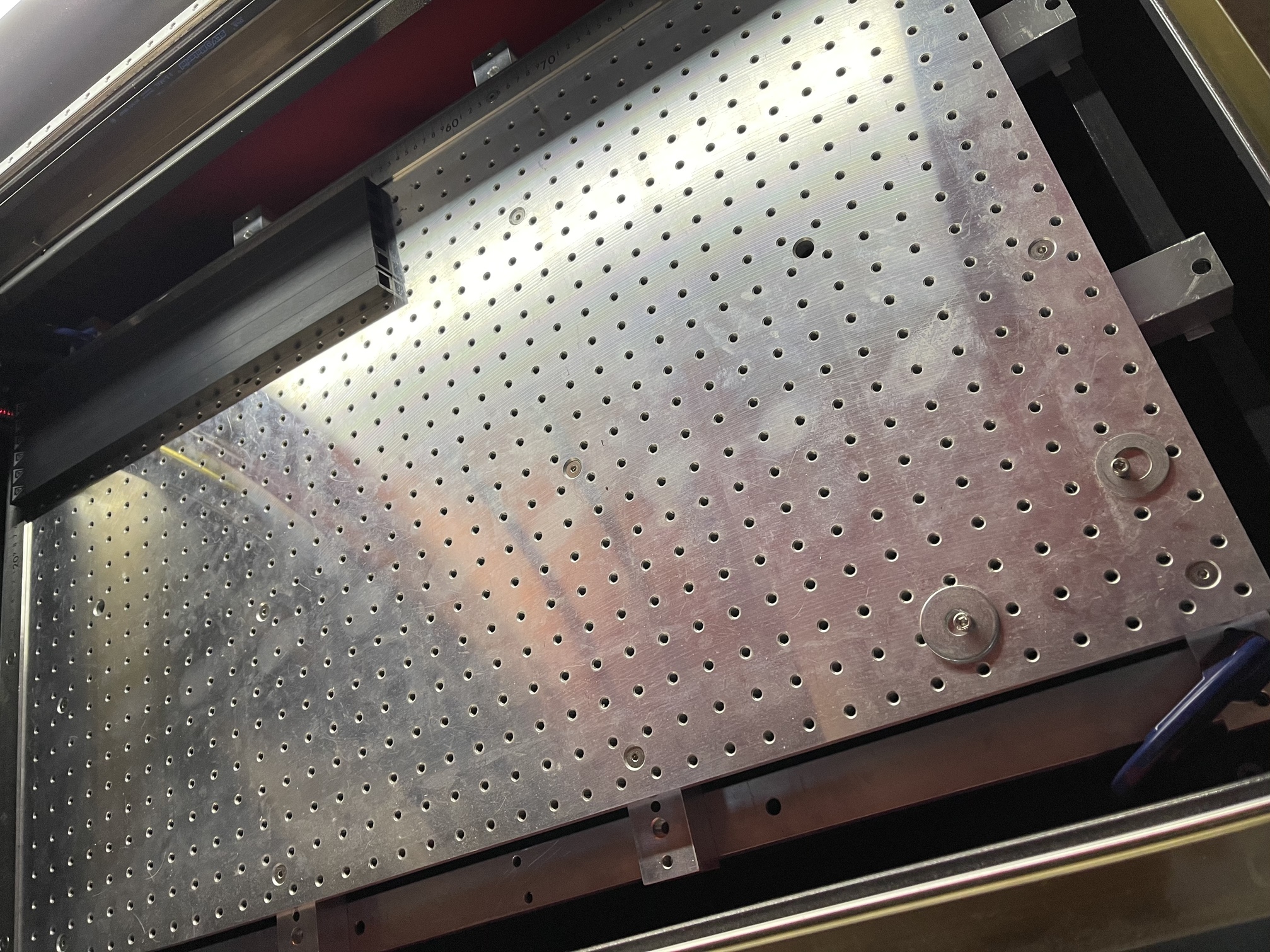
This is what our focusing tube looks like… I don’t have a picture of the mirror alignments, but if I tape a paper target over the mirror entrance, it’s perfectly centered on the hole. If I remove the focusing lens (Lower 1.5" of the assembly, just below the knurled nut in the center, and tape over the bottom, the beam is still round and centered coming out of the tube. This picture was after I upgraded the bracket with a stiffer than stock one.

Not quite. Russ did a video, and I’m not sure what for, but in it he did a series of burns at his full 70W until it no longer burned the target. That gave him the outer edge of he beam. I want to say he was doing some comparison between the RF and the CO2. But that same thing, in front of the #3 head, would tell you if you are clipping the hole with your beam at it’s farthest point. I don’t proclaim to know the actual beam diameter of my 80W, much less your 100W, or how much each expands along the way. A burn test, like a mode burn in acrylic but a paper burn in front of your #3, might give you a clue to hunt down.
I have no idea if it will or won’t, just throwing it out there as a possibility.
I’ve had that issue engraving anodized aluminum. I found that the issue was the flatness of my bed and it’s being out of parallel with the laser plane. I machined a new aluminum bed and shimmed it carefully to the gap between the bottom of the laser tube and the surface of the bed. Best upgrade ever. Now I get the same depth everywhere
If you don’t have jack screws, that’s the best you can do. Adjusting the individual jack screws can be a PITA, but at least it’s a one off job.
How much smoke is generated and filling the chamber while you are engraving? The beam passing through smoke will have an attenuating effect.
Engraving doesn’t produce nearly as much out gassing, smoke or acrylic vapor, as does cutting. Good exhaust should take care of engraving without air assist. For engraving, air assist is more to keep the lens clear than for clearing out gasses. Preferably you want a laminar flow towards your exhaust, you want to engrave towards your exhaust as well.
This topic was automatically closed 30 days after the last reply. New replies are no longer allowed.