Maybe i’m wrong but i just found that the marlin developers don’t have push the changes to bugfix 2.0.X
the file i checked is “spindle_laser.cpp”
Yours on line 85 is “set_ocr(upower_to_ocr(upwr));” as is with the changes from “Luu Lac”
While mine and on marlin bugfix 2.0.X on line 82 is “set_ocr(translate_power(inpow));”
Now i don’t know much about github and marlin code or if this have to do with my problem but i don’t have this changes.
Any desire to pull my latest into yours and start from there again?
The one thing I wonder is what your diode is going to do with only 3.3V if it wants 5V.  Mine would only go to about 2/3 power PWMing at 3.3V. I’d also up the frequency but don’t feel like doing the math that Oz would to figure out the fastest you can switch without losing an on/off event.
1 Like
I thought that the specific pin is 5v all other pins like fans etc have a resistor and they are 12v i can’t use them(only possible if i solder the signal from the laser TTL/PWM to GATE of the mosfet this is how i did it on the melzi board)…this informations is from what i have read on skr/marlin FB pages i don’t have any way to confirm this. ![]()
I will get your latest and test it i tried to do that with the version from “Luu Lac” but gives me an error
Marlin\src\gcode\control\M3-M5.cpp: In static member function ‘static void GcodeSuite::M3_M4(bool)’:
Marlin\src\gcode\control\M3-M5.cpp:84:31: error: ‘dpower_to_upower’ was not declared in this scope
84 | cutter.inline_power(dpower_to_upower(get_s_power()));
| ^~~~~~~~~~~~~~~~
Compiling .pio\build\LPC1768\src\src\gcode\control\M999.cpp.o
*** [.pio\build\LPC1768\src\src\gcode\control\M3-M5.cpp.o] Error 1
Yeah, the error I know about. He forgot to suffix one of his changes with “planner.” and it broke the build. That should be fixed in mine right now and I’ve been running the laser more or less non-stop without issue except for the one that I mentioned here when I hit stop.
The 5V output on pin 2.0 has some funky stuff going on somewhere inside. There’s some register calls that set the chip to actually output 5V but that appeared to only be run in the Servo code. You can test if you want, just measure voltage from pin 2.0 to GND and see if you’re getting 3.3V or 5.0V at 100% laser power. Disconnect laser power if you want to ensure it doesn’t turn on.
1 Like
Yeah it’s 3.35
i just measure it…
Not that big of a problem, you’re just maxxed at 3.3/5 percent right now. That said, if your controller isn’t happy seeing 3.3V, or is using actual 5V logic, then you’re in undefined behavior territory. You can get a fast switching transistor and plug 5V into it via a PNP transistor to boost it but I’m not sure about protection on the pin and all that stuff, so you’d have to google. Or get me interested in solving it for you. 
Look up a “Logic Level Converter”, they’re cheap. This is actually the one I’m using, though you only need it for a single pin:
pin 2.0 goes to the IN side where 3.3V and GND are and then 5V and GND are on the other side and OUT goes to the laser PSU.
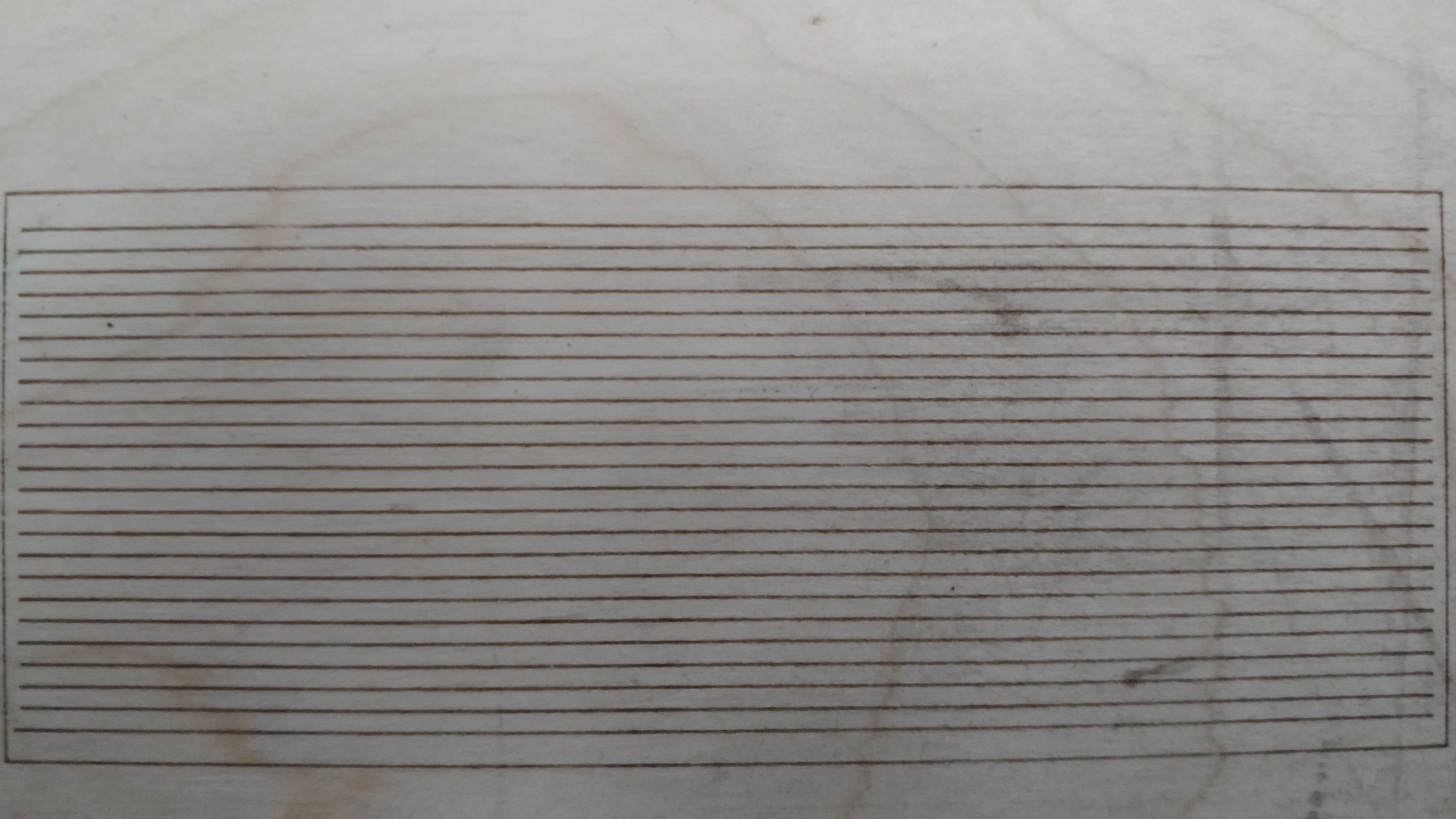
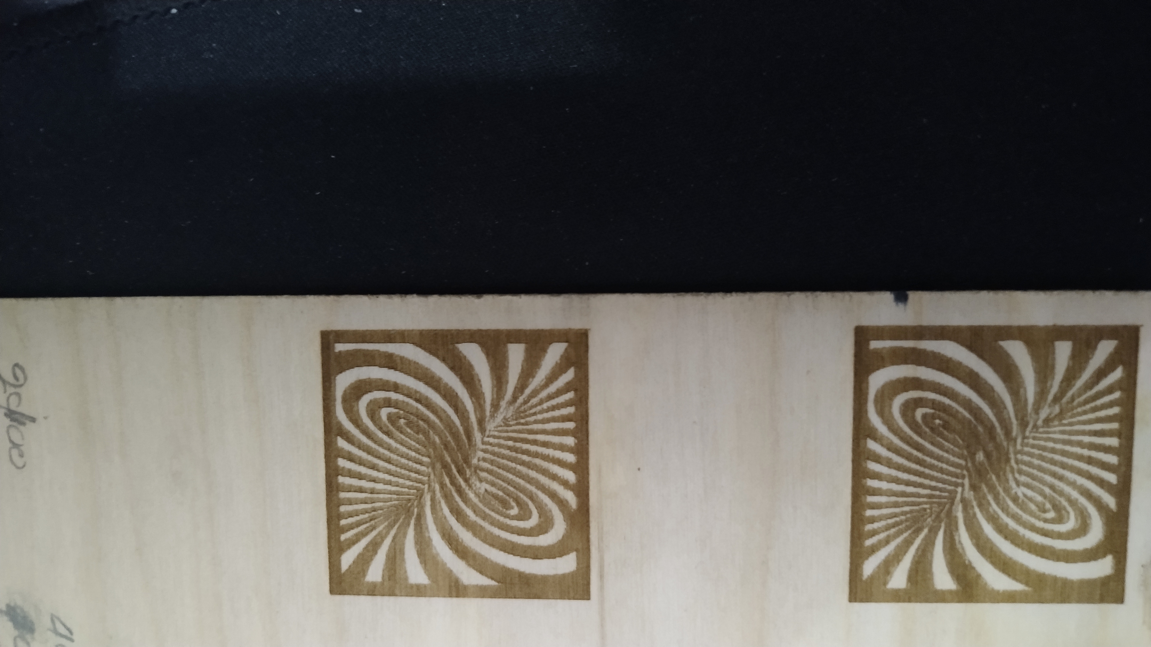
I would suggest focusing on that swirl filled thing on the left of one of the pics before going for images. If you look at the dragon in that same pic you see the right line doesn’t close, and if you look at the edges of the image ones you’ll see that they’re not crisp. A single “pixel” shift will have a pretty big impact. When you see a few in a row there and then they shift a few tenths of a mm, it will be visible.
All that said, set your min power way higher than you normally would, knowing that “min” is going to be relative to 3.3V for now. Your image is missing low-level details because 10% right now isn’t 10%. It’s .33 instead of .5. Also note that if you’re using inline to do the image your power is directly related to your speed. Slower speed less power, faster speed more power, for the same effect. Toward the end of making that image above I was tuning speed instead of intensity to get the balance between dark and light right. Not claiming it’s perfect, just something you’ll have to do as well.
The exact same gcode from your fork
I must confirm that first but it seems the best solution will be to just solder the signal to the GATE from the fan mosfet.
That looks pretty good to me! I’d do another of those filled spirals and make sure you don’t have any issues with the PWM frequency or missing steps and then go for some images! 
As for how to hook it up I’m not sure. The FAN with be powered at VIN so you may fry the diode that way.
1 Like
My understand is the fan pin - is used for 2 wire diodes to do the PWM because it has a MOSFET before it and can handle the current of switching it directly. You have an external box to do that.
If it’s putting out 5V at the gate though, I’d also jumper that. Just make sure it’s not on a conflicting PWM timer before you decide that.
1 Like
Also i can confirm that the voltage on the GATE from FAN mosfet is 4.89v but i thing the best solution is the one with the Logic converter as you mention above.
1 Like
Awesome and congrats!!
I’m just getting the new panel on my K40 cut and installed. Cut wrong 3 times. Glad I bought 10 of the black sheets lol
1 Like
Very good work
Even better from the original
Dear mentaldemise (Donald Goss)
I also built a big laser machine.
I have problems you have managed to solve and I want to help you.
Control:
Arduino Mega Ramps 1.4
with external stepper motor controller.
40W co2 tube
With 40w power supply.
the problem is that i don’t know how to turn the laser on and off at the right moment.
I think I connected the laser psu wires to the wrong pin.
I use your modified marlin version.
There are other connections on my unit like on your K40
My laser psu pin photo. MYJG-50
Currently, the arduino mega D9 pin is tied to the laser power control
the laser works with it, turns on when work starts and turns off when done, but the raster and vector fill engrav also give poor output compared to the graphic.
You can make fill work a LOT better by using the inline mode of Lightburn if you have the options set for it in Marlin.
Raster needs a faster micro controller to coordinate its steps and the laser.
This page has the config I’m using if you wanna search for “#define LASER_FEATURE” that’s where the setting start.
Yes I found the new function I currently control the laser with 106/107 but if I switch to inline it does not turn on the laser either, I was thinking about getting a 32 bit bit that makes raster processing / engraving faster
I went with a 32 bit board.
In your device settings in Lightburn there should be an option to use “inline” instead of M106/107 or M03/05, did you check that and test?
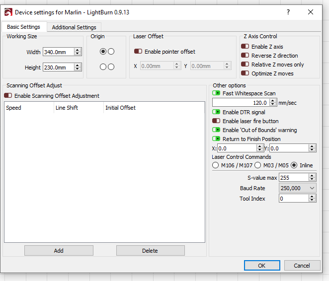
Of course, it only works with setting 106/107, with the other it does not turn on the tube.
For a reason, I’m a little desperate
Can you compare all the laser settings to what I have? There’s more than just the one setting to enable it. You also turned on LASER_MOVE_POWER and LASER_MOVE_G0_OFF? I haven’t tried to update recently, but the version of Marlin in that repo of mine was in between broken versions and had a manual fix in it. I’m not sure which version you might have. New features are awesome AND suck. 