Hi there,
I have updated my Creality Ender6 running on Marlin 2.1.2.4 on an BTT Octopus Pro V1.0 board with an LaserTree L30 modul. (I call it Ender6+)
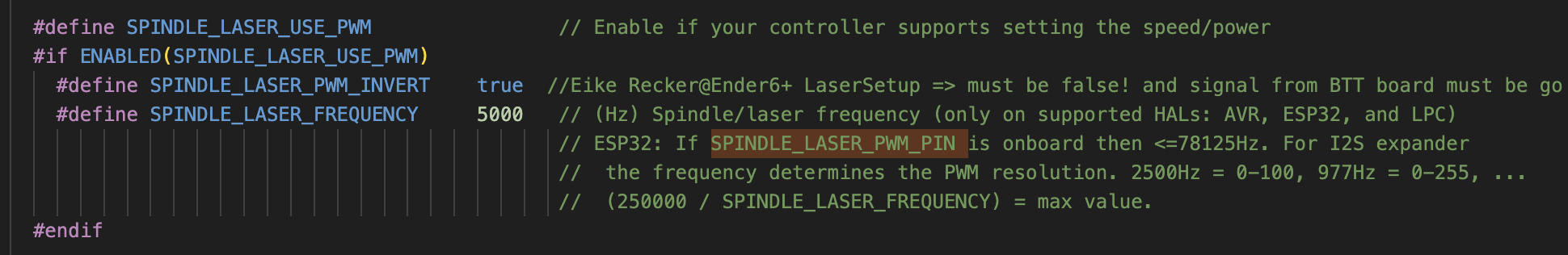
All running perfectly. Using M4 S commands send by Prontoface or using the Marlin LCD laser control menue, I get a perfectly correct PWM signal (meassuered with an Oszillocope)
I use 2 LightBurn device setups to my Ender6+
using GRBL as firmware selection in LightBurn
using Marlin as firmware selection in LightBurn
In both configurations, LightBurn connects to the Ender6+ and I can cotroll the motion. ($ commands are not working at all)
The Problem I have is, that if I send power to the Laser, the PWM signal is inverted an has a fix dutycyle of 80% High and 20% low. No matter what power setting I give to a certain layer.
Any idea what might be wrong and how I need to configure LightBurn and/or Marlin to get this wrongly inverted and fixed Laser PWM working correctly?
I just designed a very simply grafic using a rectangle and text and used 2 layers rectangle with 100% power (255 PWM value) and the text with Fill and 25% (64 PWM value)
no other settings…
howcan I check if I acidentially activated an inverse mode (does such a mode eckst in LightBurn. sorry to ask bu I am new to LoghtBurn…)
I know that in images, if you right click on mouse and select “Adjust image” you can turn it in “negative image”.
With cut and line modes I don’t know for sure. Maybe not possible.
But “inverted/negative” it was just something that come to my mind.
Thank you for your help. Actualle it can not be an inverted image or such. The PWM signal (normall gets high if laser is turnd on) regulats the power of the laser. no matter if it draws a dot of a normal or an inverted image…
Therefore the reason for my problem must be something else…
Thank you Aaron. I did overlook this parameter under the device settings for marlin. It does not solve my general problem with the PWM signal, but it explains why LightBurn did send M106 command instead M4
But perhaps the PWM signal ist not inverted but for what ever reason fixed to a PWM duty cycle of 80% high and 20% low. Thats how the signal looks like. Do you know if there is a setting which would force LightBurn to produce a fixed PWM ration instead of using the power values given by each layer?
unfortunately the PMW is correct according the data sheet of the LaserTree L30. My Osziloscope also shows the correct frequency (4.99kHz) The issue is just that the High and Low level of the PWM Signal is wrong or actually it might be that the SW is giving it a fixed PWM ratio instead of changing the PWM ratio to what I set via the layers…
I will post some pics of the oscilloscope…
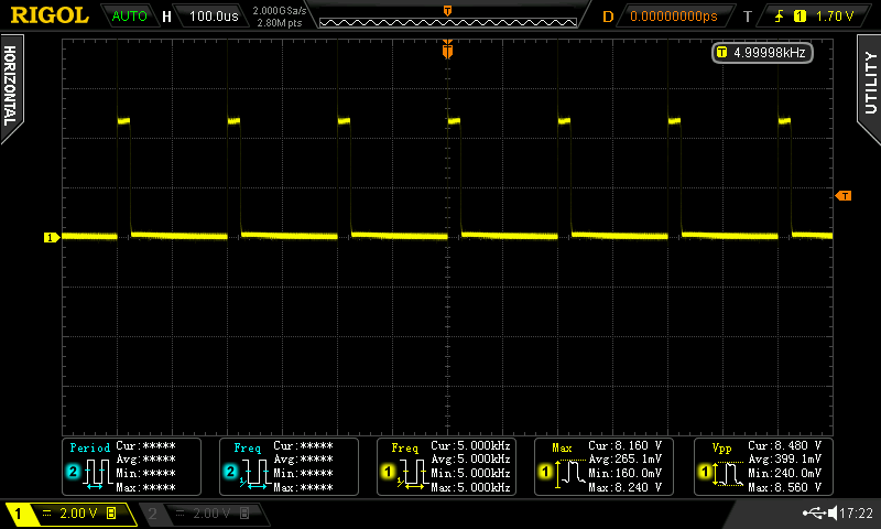
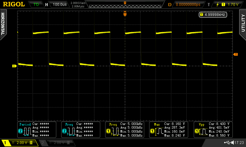
here some pictures of the correct PWM signal I need to have (created via M4 command using pronterface and LightBurn consol)
The PWM signal ratio can be set via the S parameter from 0 = off to 255=full on
so first picture shows a PWM signal creating 10% laser power (= S25) and the second picture shows a laser power of 50% (= S128)
After watch your oscilloscope pictures, those ramps at 50% mainly, just come to my mind other (maybe stupid, or not) question. Are you ready?
Could it be a faulty power source causing it?
Well, in your place I am seeing me measuring current output of power source with the scope (this is if you have the right tool for that of course. (I have, so I mention it))
Hi Kuth (is it correct to address you, or is it Luis?)
unfortunately the power supply is stabil.
I did some further testing the last hours and found out the following…
if I do change the parameter at the device settings(setup is device with MArlin FW and thanks again to Aaron to point out) this setting out to me) to “inline” or “M106/M107” I do get no PWM signal at all!? (using the device setup with GRBL as Firmware, I do get the PMW, but inverted…)
If I set the parameter to “M3/M5” (which means power allways the same, not dynamic) I DO get a corrct PWM SW.
That proof my HW setup is correct. Issu must come from either Marlin (wrong config) or LightBurn SW (no clue what it could be here…)
By the way, what did you mean with the last sentence about “me using my Oszilloscope”?
now I need to figure out why “inline” (using M4/M5 commands) is not working…
If any one could perhaps help to check if Marlin need some tweak in its config…
I don’t have a Marlin board at hand to test, unfortunately. One thing that came to my mind is your test setup. If you used dynamic power, M4, did you make sure your test object was large enough to reach the desired speed before you measured with the oscilloscope? The sense of M4 is to adapt the power to the speed, so you won’t have a constant power output. That’s why it might start with 20% instead of going to 80% directly.
Ah, I think I still have some 3D printer board lying around, I can test using Marlin, though it will take some time to get the board config done, I think I would have to do it manually.
Maybe another thing to add: Marlin support is very basic and far from “production ready”, I’d say. So it might also depend on your Marlin version. Maybe try the latest 1.x branch as well.
Hi Melvin,
thank you for your help!
I am aware of this PWM behavior using M4, thats why I want to use it
My oszi is able to show it anyway.
The proof that it is not working, is the laser itself. It does nor fire at all…
What do you mean by “using latest Marlin Version 1.”?
I am using Marlin 2.1.2.4 which is the latest available release.
I will dig deeper in Marlin code…
By the way, do you know what exactly the parameter “inline” does in LightBurn?
is it realy using M4?
Since I never used Marlin with LB so far, I don’t know. But you can easily test by creating an easy shape like a simple square and circle and export the gcode. Then turn on inline M4 and export the gcode again. Afterward you can put them side by side into a text editor and compare the difference.
To be honest, my Marlin experiences are a little bit outdated. I worked with it before 2020, I think, but now switched all printers to klipper. Back then, Marlin 1.x was considered more stable than the Marlin 2.x branch and I don’t know if LB support of Marlin 1 is better than Marlin 2.
I don’t understand your doubts correctly in this sentence (my poor english fault and translations) but what I intended to say in my last sentence is that checking the current output of power source would be the first thing I would do if I were in your skin. This is, if you have the tool (ammeter clamp) for the oscilloscope.
What I intended to say with what I wrote in that same sentence in parentheses is: I have this tool for my oscilloscope. And I only mentioned “measuring the current” because I have the means to do it.
In other words, if you don’t have a clamp meter to connect to the oscilloscope, don’t worry about what I said.
I hope I made myself understood. This thing about having to correct translations from Portuguese to more correct English doesn’t always go well, but if I don’t, believe me, it’s much worse.
So, I don’t have a Marlin as well.
Soooo I think I can’t help much more after what I read of your developments…
Thank you Luis,
I have this equipment. Current is stabil. All good with the power supply. As you can see I did a first Test and the laser and HW incl. power supply works just fine…
Only thing is M4 does not work with MArlin and LB together… I am on it…
jepp I did create very simple objects (rectangle and text) and play around with gcode export and manually changes.
It looks more and more like a Marlin issue… but I have to better understand how M4 is supposed to work with Marlin 2.