I am having an issue with my laser (100W CO2, chinese style) where it will randomly stop firing midway through a job. The laser keeps moving as if the job is still going, but no laser is firing.
I have just moved the chiller alarm to be connected to the Ruida controller instead of the lps, but the issue remains. No errors or anything on the control panel.
The electronics that lase the tube are isolated from any moving parts.
My suggestion is to go through the wiring, gently tugging on the wires looking for one that isn’t screwed down or attached properly. Generally when it’s an intermittent, it’s a flaky connection. They usually work or totally fail, so I’d guess a bad connection.
Many have the wire put in, not screwed down and the melted glue they put over the connectors are holding the wire in place… until now…
Do you have any type of test tools, like a scope or voltmeter?
Ok thanks for that, I will give that a go and see if I can spot any loose connections.
I don’t currently have any test tools, but after reading some posts on these forums I think it would be a wise investment, as I would like to be able to sort any issues myself.
Are there any connections in particular that could be causing the the laser to stop firing? My initial thoughts was the chiller signal, seeing as it was wired to the power source, but moving that to the controller hasn’t changed anything unfortunately.
I should also add that once the laser has stopped firing mid-job, the pulse button does not cause the laser to fire either. If I switch the machine off and on again, it will fire and operates as normal (until it drops out again).
Besides a common ground, there are two control signals.
The IN of the lps (laser power supply) sets the lps current maximum and is synonymous with your power setting. 50% power should produce a 50% pwm or 2.5V control voltage on the IN pin.
The L input, is the laser enable. When this goes low, it will lase at the IN current value.
A simple voltmeter should work for everything you probably need to do…
They’re cheap from Amazon… of course I think everyone should own one
Most of the Ruida control signals go active by pulling an i/o pin low or to ground.
If there is a pwm voltage and the L input is at 0V, it should lase.
All of these are measured relative to ground.
Forgot to comment on this… The flow/temperature alarms should be connected to the Ruida, not the lps. Good correction.
If connected to the lps and something happens to the chiller, it will prevent it from lasing, but the controller will continue processing not knowing there is an issue.
If it’s connect to the Ruida, it will halt all processing, so you can fix the issue and continue. With a power failure, on return of power, the Ruida will ask if you want to continue.
Ok well looks like the plan is to get a voltmeter, and then learn how to use it!
I’ll report back on what I find - or more likely I will be asking more questions along the way. I have only had the machine a short while so this is a bit of a learning experience
The machine is second hand, so new to me but definitely has a good amount of hours on it!
I have spoken to the original vendor, who has been helpful, but I would like to be able to understand and fix things myself where possible- I think that would just be easier in the long run!
Will look at getting a voltmeter asap so I can do some investigating!
If you have moved the chiller alarm to the controller, then on the LPS there should be a jumper between the WP and GND contacts. Check that this connection is secure.
If your laser has a laser pointer on the nozzle, check to see if it goes off at the same time as the laser tube. On Chinese machines, laser pointers are usually powered by LPS (+5V). Its wires are of poor quality and become bent over time, which leads to a short circuit and tripping of the LPS protection. To test this theory, you can temporarily disconnect the laser pointer wires.
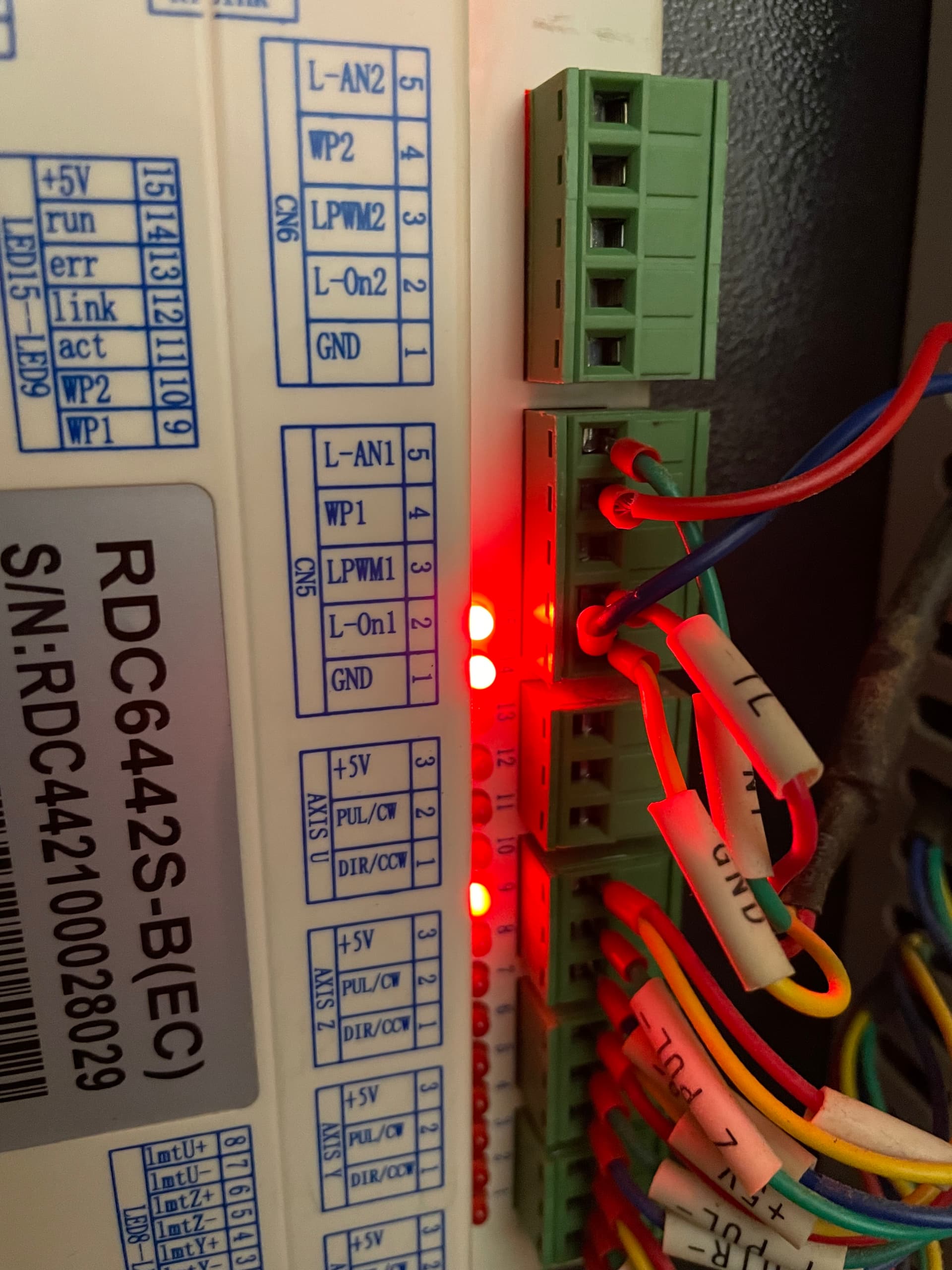
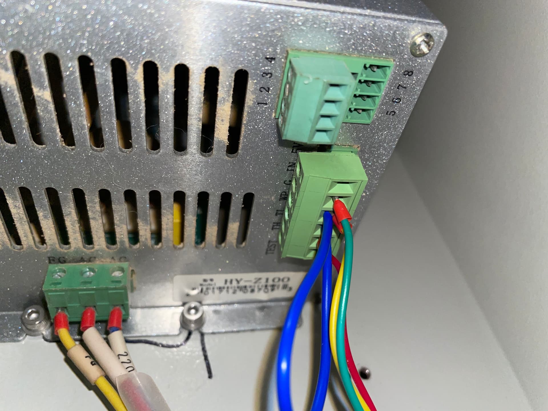
I’ll add some pics of the connections that I believe are the ones I should be looking at, which are listed below.
L-AN1 on the controller is connected to IN on the lps (green wire)
WP1 and GND on the controller go to the chiller. (red wire and blue wire)
L-On1 on the controller goes to TL on the lps (red wire)
GND on the controller also goes to G on the lps (yellow wire)
Lastly the lps has the blue loop going from WP to G.
Does that all look OK? Pics of the lps are a bit shoddy sorry - its in an awkward spot to get at.
How am I best to go about testing all these connections?
Thanks for that! Yes I have got a wire going from WP to G on the lps.
And yes I do have a laser pointer at the nozzle, but I don’t see any connection of it to the lps. I will make sure to check if it is working next time the laser drops out though incase that can be of any clue
I assume there is no arcing within the tube area? This indicates a bad tube, but doesn’t sound like your scenario.
Great, we can put you to work
The PWM has an equal output that is analog. They have the analog output to control the lasers current. It doesn’t matter, pwm is converted internally in the lps to an analog signal anyway… Measurements will be the same either way, with the same values.
50% power will read 2.5V on either a pwm or analog signal.
Yes, it looks fine…
It is working, but it fails midway through the job. This would indicate all the connection are correct and it’s got to be an intermittent wire or a failing controller or lps.
The same thing applies as I stated previously… watch the voltages on the IN and the TL inputs of the lps.
If there is voltage on the IN terminal and the TL terminal is at ground level, then it’s likely the lps is failing. The machine should be lasing when these conditions are present.
I don’t think there is arcing in the tube area…what would I be looking for here? Noise? Smoke? Marks? It all looked ok last time I had it open.
Im not sure I follow your comments on the pwm? Are you just saying that the pwm output and LAN-1 output are basically the same? Is there any reason to use one over the other if so?
I’ll do some testing tonight hopefully. So all I need to do is connect the voltmeter to either TL or IN and G on the lps terminal, whilst a job is running?
Sorry, might be a bit of a dumb question but I don’t want to go prodding things I shouldn’t be haha
You’d likely hear it. So you’re probably ok there…
Yes in this case. The lps can handle a dc or pwm signal for input, so it matters not which you use.
I tend to keep things digital, so I use LPWM1, but I wouldn’t suggest you change it.
Yes… you many have to monitor them until it fails, but I don’t know you situation. If it fails and the mechanics keep going, you could check them then.
There are no dumb questions. If you don’t know, you don’t know.
Ok so I have done some testing - I couldn’t access the terminals on the LPS easily which was annoying, I will need to do more of a garage reshuffle for that, but for now I have taken some readings off the controller terminals which should at least confirm that that is sending the right signals.
Readings are as follows
At idle
L-AN1: 0.00-0.03V
L-ON1: 4.26V
Running (working correctly) at 50% power
L-AN1: 2.66V
L-ON1: 0.24V
Running (once issue has occurred) at 50% power
L-AN1: 2.67V
L-ON1: 0.24V
So that all looks like its correct to me.
I also confirmed the red laser pointer and internal lights were functioning correctly when the laser had dropped out.
I also checked the test button on the power supply which did the following:
Running normally with wires plugged in - no laser
Running normally with wires unplugged - laser would fire
After laser has dropped out, wires plugged in - no laser
After laser has dropped out, wires unplugged - no laser
These signals, from the controller, tell the machine to lase, this would indicate the issue between where you took the readings and includes the lps/tube.
I’ve got my money on the lps… doubt you have faulty wires between the controller → lps … easy for you to check.
I’ve never seen a tube do this, but I’ve been surprised before.
Is there anything I can do to narrow it down between the lps and tube? Both are not cheap to replace unfortunately.
One other thing I have noticed is that is always seems to drop off when cutting, after engraving. This could just be a coincidence but it seems when it switches to the higher power, it will work for a bit, then drop out.