Laser stops working after continuous operation – overheating?

I searched the forum for a similar issue but couldn’t find anything.

I recently bought a second-hand YDFLP-E2-60-M7-M-R laser. The laser operates correctly and reaches 100% power, but…

During prolonged continuous operation, for example, when deep engraving at over 70% power, the laser suddenly stops emitting light after some time. The red line keeps running, but the laser does not produce any power. LightBurn does not show any errors, and according to the software, the engraving process is still ongoing.

After stopping the engraving and waiting for about a minute, the laser works again.

Could this mean the laser is overheating? If so, what can I do to fix this?
Has anyone encountered a similar issue and found a solution?

I would appreciate any suggestions.

1 Like

I do not know your laser, but this is it or it could be the power supply also.

1 Like

Could you explain a bit more, please?
What power supply do you mean, and how does it affect the laser?

The basic fiber has a laser source, control board, galvo and power supply.

Any of these could be an issue, although it doesn’t sound like a galvo issue.

The JPT I have has a circuit that lowers power and can halt the machine if there is too much reflection for it to handle.

As far as I know, I’ve never seen an error message using one of these, so it maybe that they report only on some, or not any…


Here is a JPT manual that might help… At least it’s some information on a JPT MOPA source.

How long is some time?

Good luck

:smiley_cat:

1 Like

Thank you for the helpful link :slight_smile:
“some time” means around 30-60 minutes. I’ve noticed that the higher the frequency, the shorter this time is. Or at least that’s how it seems to me.

I’ve done coins that take anywhere from an hour and a half to two hours with no issues on mine.

On a fiber, the frequency relates to pulses/mm, so I’m wondering how or if that could be a clue.

Sounds like the source is failing and there is little documentation of the internals of the source.

Many of these lasers have been around for a while and we know how all the components function, but even with these if it’s a control board, HV power supply or tube, we usually can’t fix and we swap it out.

There are only a few pieces in the machine, control board, source, glavo and power supply.

I’d check the output of the supply or monitor it when running and ensure it’s not failing. Power supplies are much lower cost than fixing a broken JPT source.

Good luck

:smiley_cat:

1 Like

Thank you so, so much for your answers :slight_smile:
I will take a closer look at this power supply.

Do you think the room temperature could also affect the power supply?
I noticed that at 15°C, the laser runs longer than at 23°C.
That’s why I started thinking about overheating.

2 Likes

I run mine above 70F all the time and even warmer. I’m in the US SW desert, so temperatures outside can be brutal, in the summer the AC is set to 78F during the day. When it’s fall or spring, the windows are open and 85F isn’t unusual.

I still do coins, when I want to, ignoring the temperature…


Heat is the worst thing for semiconductors, but I don’t think that’s the direct problem. It may exacerbate the issue, but it should operate there.

I think you should either clip your vm to the output of the power supply or when it fails, check the voltage before powering down the machine.

:smiley_cat:

I will keep observing the laser.
Once again, thank you so much for your help! :slight_smile:

Hi,

Today, the laser stopped working again. It was running for 90 minutes at 90% power, 25kHz frequency, and 450ns pulse duration.

The green LED on the power supply is on, but the laser has no output power – only the galvo is working, marking a red line where it should be engraving.

After waiting for a minute, the laser starts delivering power again.

The led is likely lower voltage… It’s probably working, but a voltmeter to ensure full 24V is there would be a good idea.

It does show the signs of overheating. This sounds like a source issue, overheating or something within the laser source…

I think this has gone past my pay grade.

Maybe one of the Ligthburn people can help?

:smiley_cat:

I’m still working to expand my knowledge of the JPT M7 series.
Do you have the manual for YDFLP-E2-60-M7-M-R? These things are MUCH more complicated than giving power to a CO2 or diode laser. The “100% power” is not really literal in that you’re not getting 60W average output because it’s set to 100%. The freq you give on the q-pulse has to match the max freq in the manual’s charts to give the max output for that q-pulse type.

What I do know is they have a number of safeties. Temp is one. There are also windows of max freq for a given q-pulse, and it does some form of limiting when you exceed it which will really mess with any testing you’re doing.

There is also an absolute max freq. I have indeed seen the beam just cut out and come back with too short of a period to really match with overheating. It’s some form of protection circuit.

And, if I read the manual correctly, “*Above the cut-off Frequency value is the fiber laser full power output range, oppositely,below the cut-off frequency value is the cut-off power output range. That means the fiber laser will
reduce the output power to protect the fiber laser when below the cut-off frequency value. Below is the chart that shows the change between frequency and output:”

It’s reducing the power if your frequency is too LOW. I picture this as it knows the fiber has been fully charged waiting between triggers and limits itself to avoid overcharging but I’m admittedly unclear on that.

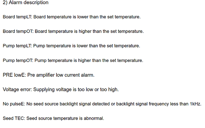
There are 2 overtemp alarms and some more exotic ones- “No pulseE, PRE lowE, Seed TEC, and Low voltage” I don’t pretend to understand what they are other than the “low voltage”. And LB has no connection to see these signals, either. LB can’t currently read any of this error info AFAIK so we’re operating blind.

On my I have indeed seen what I think is the same thing on my YDFLP-E-300-M7-M-R. At high freq, the beam just disappears for a moment and then comes back, only to disappear again, and the period doesn’t seem too regular. This went away when I reduced the freq for a given q-pulse type. I haven’t been able to get a manual yet for my YDFLP-E-300-M7-M-R yet and there’s no copy of it online so I have no chart to go by here. And also I can’t say with confidence how to read a chart either, yet, if you did have one.

But I THINK the behavior we’re seeing- beam cutting in and out at high freq- is a normal protection circuit kicking in, and there’s nothing wrong with the laser. AFAIK it is not hurting the machine, the machine is doing the cutoff to make sure it’s not going to get hurt.

The E2 machines are not the same as the E. I read a post online that they were more limited in their capabilities in certain areas. Sounds like a manual for the E wouldn’t necessarily tell you what you need to know about how to run an E2.

1 Like

Thank you for your response with lots of useful information :slight_smile:
Unfortunately, I don’t have a user manual. I only have a frequency cut-off table related to pulse duration.
I guess I’ll have to get used to this laser behavior :wink:

Do you think adding extra cooling would help?
I was considering installing additional fans on the sides of the enclosure after cutting out ventilation holes.

I hate to disagree with @Dannym, I’d be po’d if my laser worked when it wanted to, not when I wanted it to. So I think you have a fault in your source. I run mine as hard as you do and have no issues.

If @Dannym had his rf laser shut off randomly and ruin material, I think he’d know something is wrong.

I think your source is the problem, since the galvos are still operating… However I don’t know if the source actually talks back to the controller if it does fault.

I’ve had mine just over 2 years now and, like @Dannym, still learning about them.

I’m told mine will shut off if it reaches 40C internally. It also has a sensor for reflectivity, but I understand it just limits power. How much I don’t know.

I believe, these are the error status port names/pins. You could put your meter on these and see if any of them are active after a fault.

Even parts of the same manual conflict.


For example, my manual states that the both frequency limit 1 - 4000kHz and q-pulse is 1 - 500nS. However they also say …

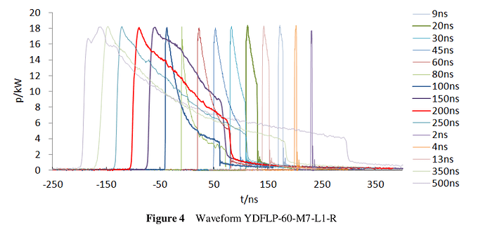
(7) The YDFLP-60-M7-L1-R contains 16 waveform: continuous, 2ns, 4ns, 6ns, 8ns, 12ns, 20ns, 30ns, 45ns, 60ns, 80ns, 100ns, 150ns, 200ns, 250ns, 350ns, 500ns

Seems to indicate they are not continuously variable values. Here is the power graph, there are only 15 entries?

Here’s an interesting video from JPT.

I believe pulses/mm controlled by frequency and q-pulse is the time the fiber is drained. My manual claims it’s highest output (power) occurs at 40kHz.

I still think you have an issue with the source.

:smiley_cat:

Correct, they are NOT continuously variable. It recognizes only the pulse widths documented, and “rounds” a q-pulse command one way or the other to one of the defined widths.

LOL I see your discrepancy in defined pulses. I was sure this was a mismatch in variants like E2 vs E but both say right there… YDFLP-60-M7-L1-R.

Actually, I think I CAN explain this. JPT told me they had to have my source’s serial number, not just the exact model number, to give me the correct datasheet. I thought that was because they didn’t want their datasheet being given to a competitor, but they said they actually changed some of the operating parameters WITHIN a model run, without incrementing the model number. So your text info vs chart could be that.

I had to wonder- JPT M7 indeed recognizes ONLY the q-pulse sizes listed. If you drive a width other than listed, say 8ns and 12ns are defined but you give 10ns, it has to be rounding to either the 8ns or 12ns. I don’t know how it selects. It could be rounding high, or rounding low, or rounding from approx the middle.

I have to note that if it was strictly round-high or round-low, then a controller giving it exactly 8ns might actually not meet the cutoff for an 8ns pulse. And we don’t know which way the rounding goes so you might get the 6ns or 12ns q-pulse. Let’s see… the logic inside the machine will see the q-pulse command start a timer, and if the pulse is still high as the timer reaches 6ns, all we know is it wasn’t a 2ns or 4ns pulse. I’d want to design it to execute the defined q-pulse as soon as possible for precision uses. Hmm, still no indication how the cutoff time might be. It would be precision to start executing one of the predefined q-pulse routine as soon as the input goes from high to low. If the internal timer clocks that as 8.32ns from when it went high, I don’t know how this works.

Does it actually initiate something physical in the seed as the q-pulse starts with low-to-high? If so, then once the counter crosses 8ns, then clocking the falling edge at 8.32ns may already be too late to execute as 8ns so it would lock it in as a 12ns pulse. So if we want 8ns, we should be entering 7ns into Lightburn to be sure we always get 8ns. But, even still, they could have baked in tolerance they’re not mentioning.

Boy, this is going to be hard to test, but I think I can come up with a test to see what the threshold is to get from one q-pulse definition to another. But… ok, hell. LB allows only whole ns in the field. I’m making a rough assumption (I could be mistaken) that my 300 follows the 200’s datasheet I do have, which is defined as 2, 4, 6, 9, 13, 20, 30, 45, 60ns… pulses. If I have a test that just shows a change in output, and I see 3ns and 4ns are the same and it actually increments at 5ns, that doesn’t tell me whether 5ns is rounding to the 4ns or 6ns profile.

It would require that FIRST I do 17, 18, 19, 20, 21, 22, 23 ns and see where it changes. Let’s say I see the 17-20 are the same and it changes at 21. I actually DON’T know if 21ns in LB is giving the 20ns or 30ns profile. It could be rounding either way. But the scale is not evenly spaced, and that’s how we decode this. If I keep increasing time, then if the next transition to a different output is at 31 ns, then I know the 21 is rounding to the 20ns profile and 31 is producing the 30ns profile. But if I don’t see a transition until 36, then that means 21ns was rounding UP to 30ns in the first place. 31 would still round to 30ns, as would 41- because there’s no 40ns profile defined. The next profile is at 45ns so seeing the output change at 44-46ns instead of 29-31ns fundamentally exposes whether it’s rounding up or down.

This sounds like obsessively splitting hairs, but no, it’s basic and essential. We just had a cold snap and it’s below freezing in the garage now, too cold to run it to re-test. IIRC, I think I saw the source start dropping out when I put 9ns in and used the “Max Bandwidth” of 4000KHz for the 9ns. Well, it may have clocked that at 9.07ns and rounded that to 13ns, which has a max bw of 3000KHz so a limiter would be tripping. If that’s how rounding works, I need to enter an undefined 8ns to be sure to be recognized as a 9ns profile.

The user also needs to understand this if they’re testing settings. LB also needs to understand this. You shouldn’t bother making a grid of test squares stepping rows as q-pulse from 2ns to 30ns by 2ns, because (let’s use your text) even if 2ns got the 2ns profile, then the 2, 4, 6, and 8 rows are useful, but the 10 is pointless since it’s a repeat of 8ns, 12ns is useful, then 14, 16, 18 are pointless repeats, then 20 is valid, then 4 more pointless rows.

LB needs to be able to be configured so the config has an array of arbitrarily entered q-pulse options. The settings should only let you select one that exists, and if you do a power test grid with q-pulse as an axis, it should only sweep through the defined q-pulse options.
Also, the datasheet I’m working from is for the 80,100,200 whereas I have the 300. The only source I have for this is a crappy pay-for-doc site I can’t download from: YDFLP-E-80&100&200-M7-M-R User Manual V1.0 | PDF

It lists a “Normal” and “Performance” mode. Performance mode is around +20% more output, but is a more limited operating temp range. I don’t see how LB has any control or visibility into that. The JPT M7 manual refers to a GUI of their software that controls “Performance” mode and has a BUNCH of useful operating info. Temps, currents.

That seems to operate through an RS232 COM port on a separate DB9 interface. The BJJC galvo controller that LB/EZCAD talks to uses the M7’s DB25 to control power and has some “trouble” flag pins. That plug doesn’t have the COM port so this interface is unavailable.

Plugging in an RS232-to-USB dongle is trivial, but it would need “JPTLaserGUI.exe” and I don’t have that. The message protocol is not documented so the JPT software looks essential.

OK, I see more- I have it wrong, the pulse control to the M7 is NOT a pin going high and low. It’s serial data, so 6ns has no ambiguity of rounding how long that counted out to be by the laser source.

BUT… check this out!

“The parameters of this instruction are the binary values of the pulse width. Users can compile any values of pulse width, but the laser can only receive the signals of specified pulse width (please refer to the user manual for specific pulse width). If the value of pulse width is out of the range of specified pulse width, the laser will choose the default pulse width set last time.”

LOLWUT. Boy, that can trip you up! It’s not rounding in either direction- it could be rejecting your value and using the last one??

1 Like

I thought all the data was shipped over an 8 bit parallel data path…?

I also have no way to measure these pulses :face_with_spiral_eyes:

Did you get the proper manual? Seems if you are in communications with jpt, they’d have the manual available.

I am a bit handicapped when it comes to running Windows software as I run Ubuntu Linux. I did come across this.

For those that don’t know, this is an .rar type file, so remove the .txt extension.

JPTLaserGUI20220104_E.rar.txt (4.2 MB)

Found it here:

Let me know how it works, it’s supposed to be for the E series, but I don’t know any more about it.

I’ll be waiting for your feedback.

:smiley_cat:

We have a few reports of this type of behavior but I have not seen a solid solution that prevents it from happening.

It could be caused by an unreported high temperature safeguarding event. If we’re not seeing an error message on the serial communications link, the software can’t elevate it to the user.

1 Like