I am considering purchasing this laser module [LT-K60] to replace the 33W laser module [M150} on my Atomstack X30 laser engraver. I have downloaded the user manual for the K60 but I am still somewhat concerned and confused about connecting it to my X30 control board. The pin out on my X30 is five [5] pin and I do not know what each one of those wires in the 5 pin configuration represents. I see that the K60 has a 3 pin input on top of the laser module [PWN-GND-24V] - and I assume that in the kit there is a 5 pin to 3 pin - or 5 to 4 then 4 to 3 pin reducer/adapter. My concern is that they are in proper alignment wire to wire so there is no potential damage to the K60 laser module or my existing controller board for my X30. Looking at the top of the M150 laser module and the 5 pin connection - I don’t know what each one of those wires represents. If anyone knows, say from left to right, that would be great - or any other affirmation of the wire representation would also help. I own 4 diode laser engravers, an LP4 Laserpecker, and one CO2 laser engraver and have been doing this for close to three years now so I’m quite capable of making any potential necessary changes. I’m simply looking for specific details on the connection process. There is nothing on YouTube. Any assistance and help in this matter is greatly appreciated. Thank you.
Both of these lasers claim the same signal connections, ground, power and pwm.
Since the LT-K60 draws 10 amps of power, it’s likely it has doubled up on the input. Meaning the connector won’t carry enough current, so they double up ground and power. That would be 5 connections.
The LT-K60 also states it uses a MR30 Port (DC24V,FND,PWM) type connector. The atomstack information shows which connectors do what.
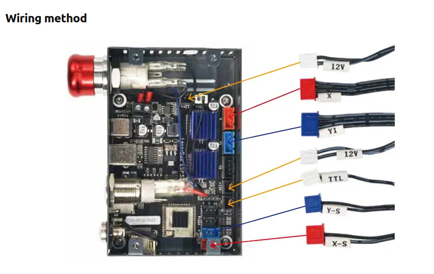
You need to find out the pinout and the type of connector for the LT-K60, as they don’t specify which pin does what. Maybe it’s in the package???
The new module draws 24V@10A, not sure if your motherboard can supply that amount of current.
![]()
What happens with doubled pins in those teeny connectors:
- One pin makes a slightly worse connection than the other
- That pin has higher resistance
- Which means more heat
- Which hastens the corrosion
- Which increases the resistance
- Eventually, the other pin carries most of the current
- Which means more heat …
Which is why outboard adapter PCBs with beefier connectors for the power supply and laser head make sense.
Did say it was a good idea, but many are doing that exactly.
The advertisement stated it uses MR30 connector, I use these myself. Supposedly they handle around 30A.
![]()
Based upon your response, I believe you’re suggesting that I use the board that comes with the laser tree module and the power adapter that comes with the laser tree module. Correct? I don’t know what the amperage of the M150 uses, as you indicate the laser tree uses 10 A. So you’re suggesting that I don’t use the control board that came with my X30 pro. Here is the link to the manual for the laser tree module I purchased [LT-K60] click on the LT-K60 . Possibly information in there could provide you with a little more insight, if you have the time to check, if there’s something specific that I would need to do with the wiring output of the X30 pro controller. Greatly appreciate it Jack
Much more juice than a typical knockoff JST XH!
I suggest you use the supplied driver board. All it does it separate the power so it’s not drawn from the control board.
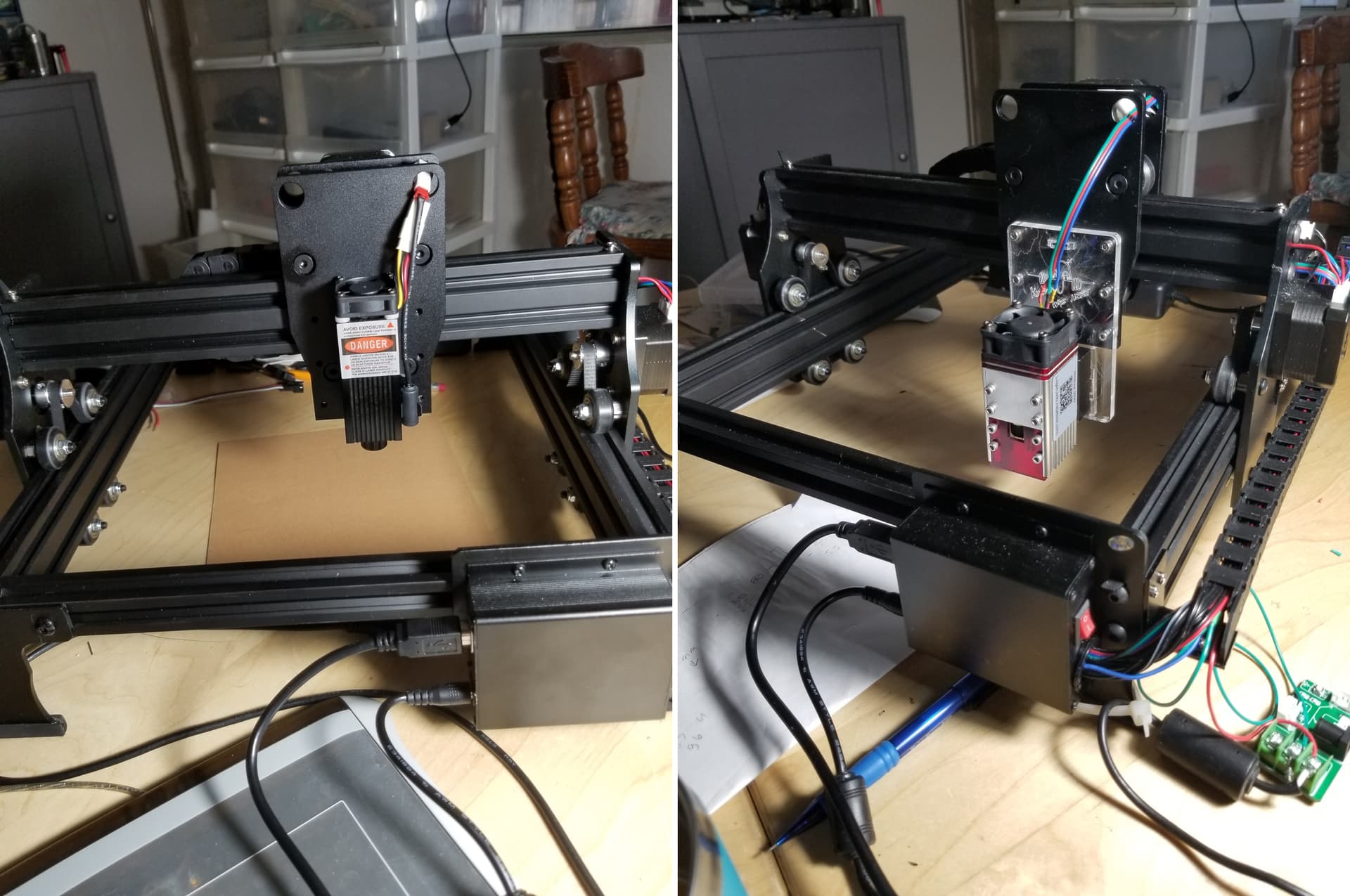
I converted a JL1 from a 500mW to a 5.5W NEJE 40630 module that required the power be separated as the control board can’t supply enough current. You can see the small board on the bottom right.
It appears to have connectors with it from the manual.
![]()
Thank you Jack. That’s what I will do. Keeping my fingers crossed all goes well and smooth. But I do expect speed bumps as there is in almost everything one attempts to do and thinking things will go smoothly.
Just pay attention to the plugs. Usually they are very clearly marked, if you have a question, ask.
![]()
Thank you. I’m going to check the details of the power adapter that Atomstack provided with the laser module and compare it to the power adapter specs on the X30 Pro power adapter provided with my Atomstack laser engraver. So possibly I may not only use the board, but I may possibly use the power adapter if there is a discrepancy.
On mine, without surgery, these boards separate the supply from the controller and use the supply that came with the laser. Generally you cannot just put a larger supply (current) on the controller board.
Normally these control boards cannot supply enough current to the device.. This is because of the copper trace thickness, there is a limit to how much current they can safely supply to the laser.
Good luck
![]()
That confirms that I will use the PCB board that comes with the laser tree 60 W output laser and use the power supply adapter that they provide and connect that to the PCB board. Got it. Thanks again. If I’m wrong, let me know. It’s happened before ![]()
I bought one and it died a week after. I sent several emails to Lasertree and got no response at all. I finally went on Facebook and got in contact with them and still got no help. I mean this thing died in the 30 day return policy window and they didn’t do anything to help. I have a $900 brick. If I were you I’d avoid this company!!!