Hi!
My first post here. I am a newbie but I absolutely love Lightburn so far.
My laser is a cheap Chinese one called Laseraxe (diode). I am running GRBL 1.1h.
In my device list when I choose “GRBL” the laser won´t stop between cuts leaving a line. It looks like it is using 100% power between cuts. And it won´t stop after finishing the job leaving a burnt hole.
If I choose “GRBL M3” it works fine but corners etc are not as nice.
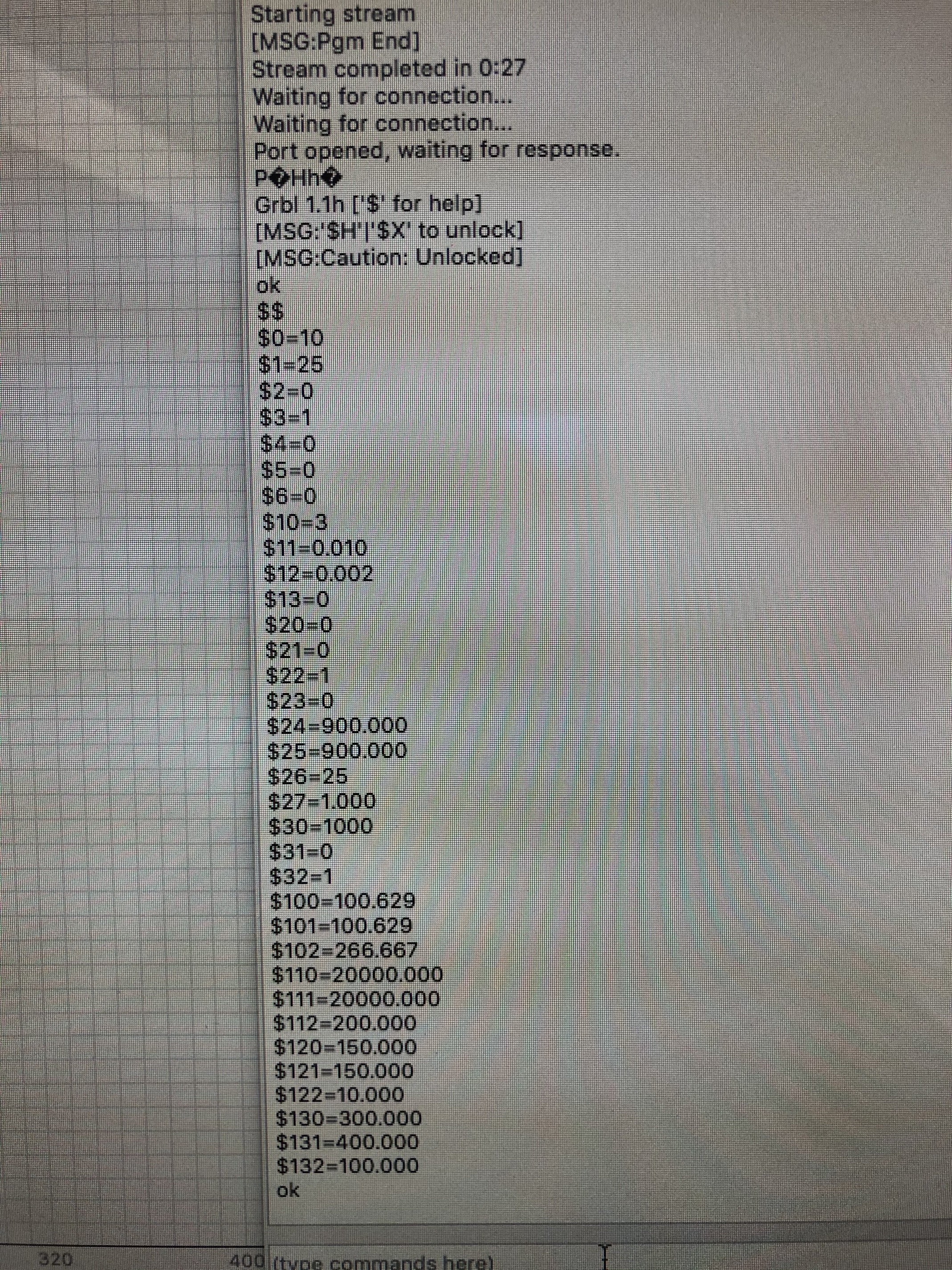
Am I missing something? $32=1, $30=1000 as is s-value max in Lightburn.
Is my laser unable to run using variable power mode?
That’s very strange - your settings look correct, but it looks like the laser is completely ignoring the PWM output and just turning on & off. Is it wired to the wrong port? Sometimes they have one called “laser” and one called “fan” or “pwm”. The 2nd one is actually the one you want, bizarrely.
If you use GRBL-M3, does it control the power correctly? 1.1h might be a custom version made by the manufacturer instead of the actual, proper 1.1h that’s been recently released.
Thank you for quick reply!
Very strange indeed. I will check if I am using the wrong port.
Grbl 1.1h is the ”original” one. I have installed it myself.
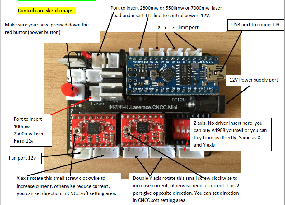
Ok, so I checked my port. It looks like the right connections. Pictures below shows pin out for the Laseraxe board found on www.laseraxe-customize.com. Don´t know how reliable they are though.
My laser is connected (according to the first picture) to:
“Port to insert 2800mw or 5500mw or 7000mw laser.”
“Head and insert TTL line to control power. 12V.”
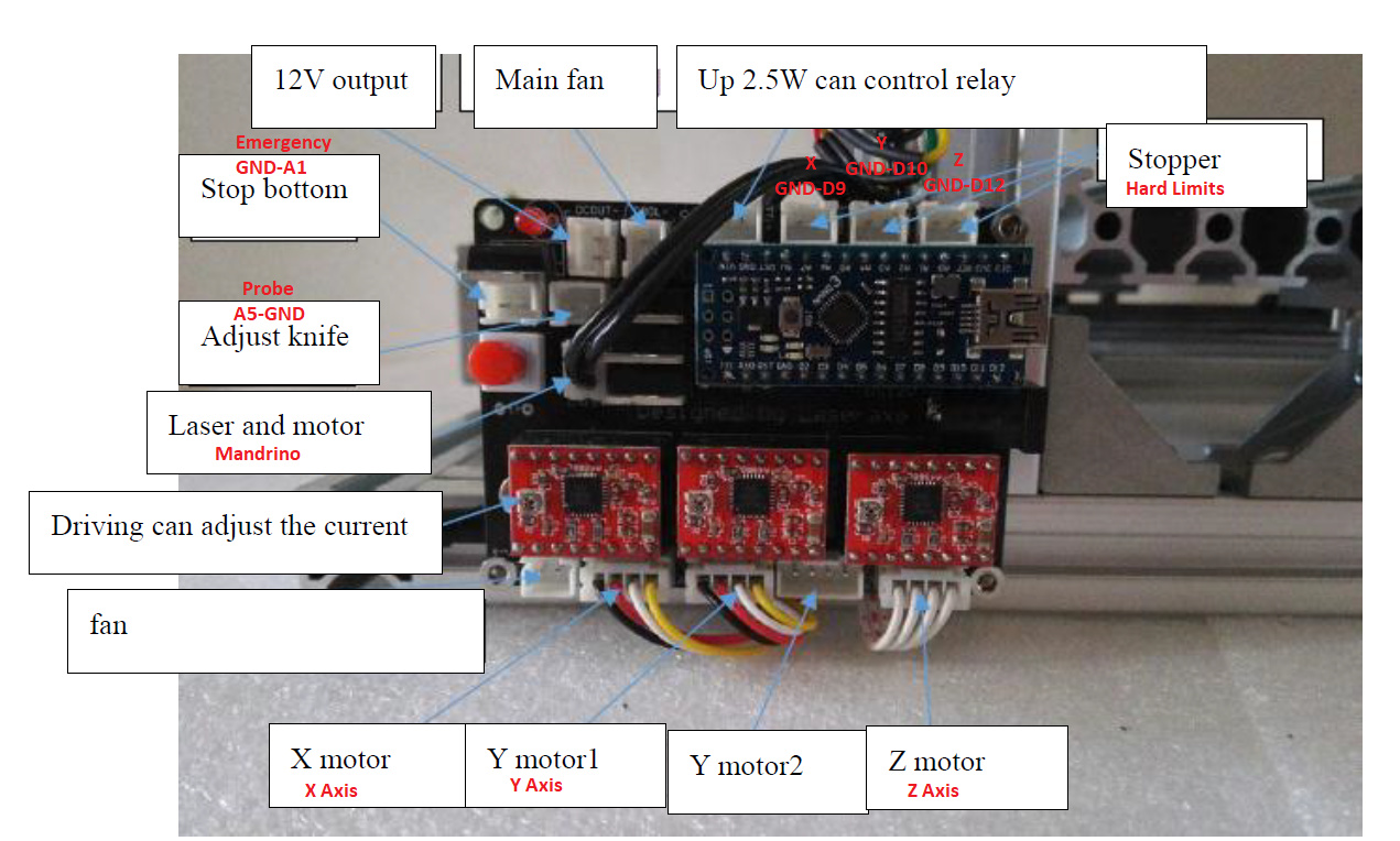
The second picture shows a port called “main fan”. Maybe I should try that one?
(My laser was sold as 7W diode.)
Henrik
It says, “AND insert TTL line to control power” - I’ve only ever seen systems that use the PWM output, not the TTL line, though I don’t think that should matter. Check that the TTL plug is seated properly and is actually connected to the laser too - if that didn’t work, it would cause all the problems you’re seeing.
Aha, could it be that I need to connect a second wire to that port? Now it is only connected with one (red) wire. (It is a bit hard to see in the third picture.)
Is it possible that my laser module doesn’t support ttl/pwm?
It was bought as a kit. That Connector is a 2 pin molex but with only one wire connected. I Will check continuity on that single wire tomorrow and report back. Thanks!
Ok, so now I have measured some voltages on my PWM line. It seems that when in “GRBL M3”-mode the PWM line is acting normal. Steady voltage when cutting and 0V when moving and finishing.
When in “GRBL”-mode the PWM line is inverting the signal. Variable voltage when cutting and close to 5v between cuts and when finished.
Is there some sort of setting I can change to invert the PWM back? (I read about some little circuit including a FET transistor but would rather do it in the software if possible.)
I pulled it from their site. But I had to change the pin map for my laser to work. It was a while ago because I rebuilt my workshop. But I remember just copying the pin map from my working version.
And it is still working as supposed in GRBL M3-mode.
I am by no means a programmer.
What is the difference between the “GRBL” and the “GRBL M3” in terms of PWM?
As far as I know, there shouldn’t be any difference in the PWM output range. GRBL-M3 uses the M3 (constant power) command to set the PWM to a specific rate, and turns the beam off & on using M3 / M5 commands. The normal “GRBL” driver uses M4 (variable power) to set the PWM output, and this is varied as the speed changes. When the head is not moving, the power output is automatically off. When the head is moving at the requested speed, the power output is 100% of what you requested. This provides much more consistent output when doing surface marking of vectors, because the power is reduced for sharp corners.
So my problem must be that M3/M5 command is working with my laser but M4 is not. My other problem is that I don´t know what they are. I have some reading to do.
By the way, thank you so much Oz for helping me!
From the link above:
“* When not in motion, M4 dynamic mode turns off the laser. It only turns on when the machine moves. This generally makes the laser safer to operate, because, unlike M3 , it will never burn a hole through your table, if you stop and forget to turn M3 off in time.”
Haha, that is the exact opposite from my laser.
I can not figure out this problem. Just to recap:
In “GRBL-M3-mode” everything works fine. The laser turns off between cuts and turns off when ready.
In “GRBL-mode” The laser burns with full power between cuts and when returning to starting point after finished job (burning a hole in the table). The only way to shut it off is to pull the usb.
The PWM voltage is variable when cutting and close to maximum (5V) between cuts.
Something is happening with the PWM when I use “GRBL-mode”.
If I understand it correctly M3,M4 and M5 uses the same pin on the Arduino. Maybe I have to change something in the GRBL file in the Arduino software?
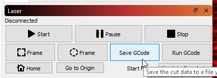
Can I see the g-code generated by Lightburn? If there is a difference between “GRBL-M3” and “GRBL”.
LightBurn does this for you in M3 mode - it sends M3/M5 pairs for cuts. If you scan a shape like the letter O, it might not turn off in the middle, because I use S0 / Sxxx commands for that, instead of M3 / M5.


 Were they sold as a matched pair, or bought from different places?
 I have some reading to do.