I was wondering how to turn my LBRN or LBRN2 files into a quick reference guide so I don’t have to open up the file to get the settings. Since the LBRNx files are XML based, is there any documentation on the schema or has anyone written any code to document a project.
1 Like
Both file types use the same overall structure, and the cut settings are stored identically.
If you open an LBRN or LBRN2 file in a text editor and look for CutSetting it should be pretty clear how the data is stored. If you have any skill with Python at all, writing something to read the files wouldn’t be hard.
I used MSExcel to read the file and had it generate a schema for me. As you pointed out, the CutSettings have all the info I need! Many thanks Oz!
JoeG
1 Like
What type of vectors is lbrn using? I want to batch generate lbrn files that should be used in a workday, but can’t figure out what type of vector this is. Other data in lbrn xml is quite clear.
For example, I wonder how I get this part from regular svg:
    <Shape Type="Path" CutIndex="0">
        <XForm>1 0 0 1 0 0</XForm>
        <V vx="357" vy="141" c1x="293.41559" c1y="102.6198"/>
        <V vx="439" vy="111" c0x="524.99817" c0y="109.78444"/>
        <V vx="485" vy="192" c1x="533.95715" c1y="154.33014"/>
        <V vx="406" vy="220" c0x="342.98444" c0y="295.81232"/>
        <V vx="325" vy="196" c1x="341.15182" c1y="209.83997"/>
        <V vx="276" vy="172" c0x="269.35028" c0y="135.61481"/>
        <P T="L" p0="0" p1="1"/>
        <P T="B" p0="1" p1="2"/>
        <P T="L" p0="2" p1="3"/>
        <P T="B" p0="3" p1="4"/>
        <P T="L" p0="4" p1="5"/>
        <P T="B" p0="5" p1="0"/>
    </Shape>
when I export the 6-anchor point shape I get svg:
<?xml version="1.0" encoding="UTF-8"?>
<svg xmlns="http://www.w3.org/2000/svg" width="239.788mm" height="139.888mm" viewBox="-514.719971 110.976334 239.788055 139.887894">
    <path
    transform="matrix(-1,0,0,1,0,0)"
    style="stroke:#000000;stroke-width:0.05mm;fill:none"
    d="M357,141L439,111C524.998169,109.784439,533.957153,154.330139,485,192L406,220C342.984436,295.812317,341.151825,209.839966,325,196L276,172C269.350281,135.614807,293.415588,102.619797,357,141z"/>
</svg>
1 Like
V is “vertex”, or a node / point that is part of a shape. P is “primitive”, which will be either a line (L) or a bezier curve (B) connecting the points together.
On the vertex, vy and vy are the x and y values for the point, and c0 and c1 are the control point handles coming out of that vertex, if used.
This is how a circle is defined in LightBurn, using four vertices, and four primitives. Each vertex has two control points (C0 and C1) coming out of / into them:
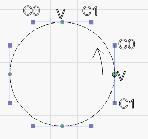
This curve goes from V → C0 on vertex 0 to C1 → V on vertex two, then from V → C1 on vertex two to V → C0 on vertex three, and so on.
In your SVG, the C command in the path definition does this:
M 357,141 L 439,111 C 524,109,533,154,485,192
The first command is M for Move, then L for Line, then C for Curve - It Moves to (357,141), draws a Line from there to (439, 111), then draws a bezier Curve from there through control points (524,109), (533,154), to a point at (485,192).
A Cubic Bezier curve is always 4 coordinates - the two end points and the two control points. After that it’s just figuring out which ones go where.
1 Like
Woho, that was extremely fast! Appreciate.
So if I get this right, this is not a kind of standard vector format? Is there any lib to handle svg => lbrn format vector conversion?
This topic was automatically closed 30 days after the last reply. New replies are no longer allowed.