Lead on/Lead off headaches, climb vs conventional, pocket vs boss


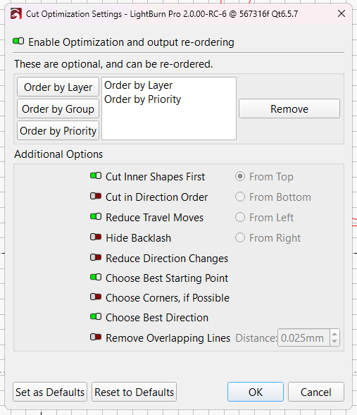
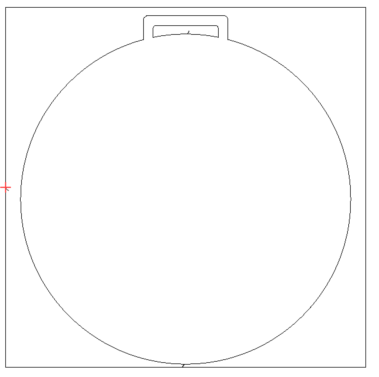
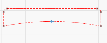
This is the shape I’m attempting to preserve.

I have it nested within a larger rectangle for a clean offcut (which can get scarred by bad lead-on and won’t cause problems in our production line)

I come from a machining background where I run CNC lasers, Plasmas, Waterjets, mills, and lathes. So I’m used to climb cuts on everything and arcing on from a positive radius.

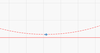
When dealing with contours we usually arc on from the left side of the cut line. This means that we run clockwise around an external contour, and anti-clockwise around interior pockets.

Thus my expected behavior is…


When selecting the following starts and directions:

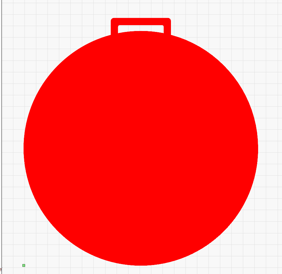
However, reversing the direction does NOT flip the lead on to the other side of the contour.


My question is this… what precisely does Lightburn use to determine interior versus exterior contour?
I’ve attempted to toggle from line to fill and use the boolean functions.
I’ve also attempted to group specific geometry, while leaving other geometry ungrouped.

This is becoming quite an issue for us as we’re pushing out tons of new products and having to hand-hold each one, and add additional cut layers with the same speed/power settings, and all sorts of other hoops to jump through.

It’s really bogging down our efficiency on the much more complex and intricate cuts especially when we cannot get the lead on to flip to the correct side of the line on EVERY geometry with a single layer.

To go through our back catalog would be egregiously time intensive at this point, so is there another way to get the behavior I’m expecting consistently rather than using 2 separate layers with opposite direction lead on/off’s?

Cut Example.lbrn2 (12.4 KB)

AIUI, LightBurn assumes you start with a big sheet of stuff, from which you will cut an interesting (closed) shape. The perimeter of the shape is its outside border, so applying a positive kerf correction will make the shape larger by removing more of the big sheet material you don’t care about.

Another closed shape within that border puts a hole in the shape, so its border is considered inside: a positive kerf will make the inner shape smaller to maintain the proper size of the enclosing shape.

Again AIUI, count the number of line / curve crossings from outside all the (closed) shapes to the inside of the shape you’re interested in:

  • Odd number of crossings → the shape is outside
  • Even number of crossings → the shape is inside

In your example:

  • The enclosing square is outside = stuff you want (which is incorrect)
  • The circular shape is inside = a hole in the stuff (which is incorrect)
  • The little piece in the handle is outside = more stuff you want (which is incorrect)

Removing the enclosing square will make LightBurn’s assumptions match your reality:

  • The circular shape is outside
  • The little handle shape is inside

At least that’s how I think of it, which could be upside-down and inside-out. Other folks may have a better explanation. :puzzle_piece:

The Cut Optimizations settings may be working against you:

The Choose Best Starting Point setting lets it start anywhere, rather than at the first node of each shape.

Then the Choose Best Direction setting allows the cut planner to pick whatever direction it wants for each shape, overrriding the direction you picked.

I started out turning on All. The. Optimzations., but it seems they can work against each other to produce weird results, so I’ve backed off a bit.

In your situation, you may want to flip the Enable Optimizations switch Off to force the planner to use your shape start points and directions.

1 Like

Alternatively, put the enclosing shape on a separate layer to achieve the same result while retaining the shape and cut.

Hi Scott,

The settings in the example file you attached look ok?, the -90 degree lead in will set an internal lead in, which suits what you are doing.

The start point for the outer box needed to be moved - I inserted a node (using ‘m’ to create a node at the midpoint while in Node Edit mode) in order to move the start point away from the corner (where internal lead-in’s won’t work).

Is this what you wanted?

The box is irrelevant.

What I NEED is for the lead on to always be the SAME 90 degrees off the starting direction.

Not for something to override that and make an assumption about a particular piece of geometry.

If you flip the direction -90 becomes oriented +90 to the actual direction.

That’s fundamentally what’s the issue.

How do I correct that behavior?

What setting did I overlook that allows the software to determine whether something is a piece or a knockout?

Trying to avoid that as per reasons in OP. Workflow already established, going back through the archives, yadda yadda.

Did I sell you your OMT back when I was working there? Name is strangely familiar.

Ya the assumptions LB is making is what’s the root of the issues.

Tried disabling optimizations didn’t help sadly.

Not gonna say “can’t” make different layer. Just problematic for reasons. Short version, only 1 person has access to the master production software that kicks out the individual vectors. And it’s NOT me. Otherwise this would be a different conversation.

Misunderstood that portion from the OP. But may be less time intensive than having to review every single time or potentially have to rerun a botched job.

Also, if you have a high volume workflow that is extremely sensitive to cut direction with leadin/leadout I’m not sure having LightBurn in the mix dynamically generating the cut path and running the job is ideal. Any version change or possible setting change could disrupt your intended job. You may want to consider a workflow that preserves known good RD files and run from those as those will run the same way every time. Just food for thought as you obviously know your own needs best.

The outer box is exactly relevant, because it causes LightBurn to regard the disk shape as a hole.

Got the machine through Amazon and they made me as anonymous as possible.

I seem to have one of the eight standard faces, though, because too many folks think I’m someone they knew long ago. Surely that didn’t come up in the transaction. :grin:

By irrelevant, I meant that this “sample” file is just that demonstration of the problem.

The production files in question are proprietary (so I can’t release them here on the forum) and way more intricate. Even without clean cut borders have issues determining line side.

Oh if you bought through AMZ might have caught you on the support line if there was a delivery issue, or if you had an issue that got escalated out of the AMZ support team to the domestic team.

Ya the personnel situation complicates things.
From lack of explicit design guidelines, to deviation in process, lack of recordkeeping when things change. Growing pains of a small company ballooning. Also the typical “but we’ve done this this way for months” kind of thing.

HEAD->DESK

Oh, yeah, there was some of that … :grin:

Fall off a lift gate? Or did it get delivered with no lift gate?

That part worked fine, but the trucker somehow didn’t get our address / phone and Amazon makes it impossible to communicate those things through their messaging service. You may have un-wedged that whole mess. If so: many thanks! :check_mark:

I had the same issue trying to keep ‘kerf left, save (part) right’ when I was using modified LB gcode for plasma process. That was a couple years ago, but I recall Layers playing a key role for establishing the set of shapes (contours) where LB handled correct alternating of kerf offset on progressively nested interior contours, that is… correct provided I began with correct kerf offset (inward or outward) with the outer most contour. Cut direction however is a crap shoot, seems like I recall tool drawn shapes always having [corrected] CW direction, while text had CCW w interior reversed. For these reasons and other CAM UI difficulties or absent features, I use another CAM now for plasma toolpath, but still use (for plasma) LB as 2D CAD and for CAD/CAM with laser.

If you did everything through email/amz messaging, then it likely didn’t hit my desk. If there was ever a phone call.. you’re welcome. Glad it got to you :slight_smile:

OK thanks for confirming I haven’t lost my sanity coming from the G-Code world.

Can we get Jason to chime in on his design intent here. What exactly is happening behind the scenes and that this behavior is intended? And what his recommendation is?

I really don’t want to have to give up a layer If I can at all avoid it by flipping a start direction. and having lead moves orient with the cut direction instead of the orienting themselves to the perceived contour.

Unless I understand this wrong (which is entirely possible given the convolution) you set the kerf offset inside/outside at a layer level. So in this case, use two layers. Are you approaching the layer limit?

Our delta we will approach the layer limit before the end of the year if we have to use a second layer for the same cut settings just so that we have granular control of the lead on move in reference to the cut direction.

Again, the complexity comes from further up the software chain where the cut files are being generated to facilitate custom cuts and have files output that are LB friendly so our operators can drop them in and hit “start.”