New Lightburn user and working on setting up an Opt Laser on my CNC router which uses UCCNC for control software and an AXBB-E motion controller.
I have everything working hardware wise and sorting out the Custom Gcode configuration. I will be saving out Gcode and taking that to the CNC and running it independent from Lightburn.
I have generated Gcode to successfully cut rectangles so I know most things are working as they should.
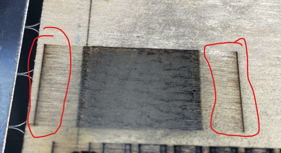
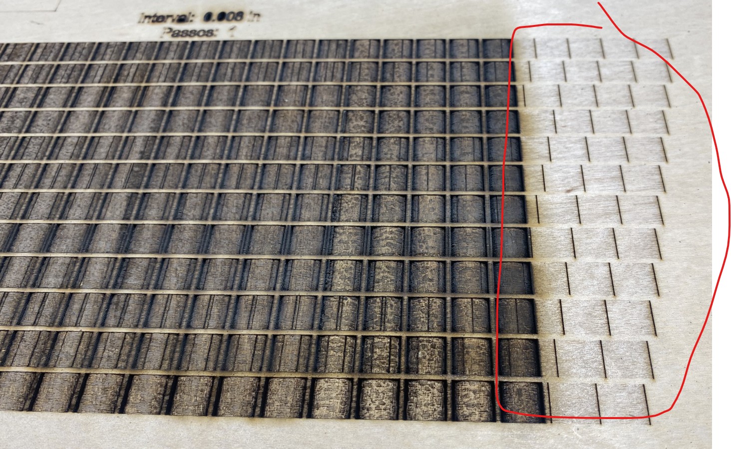
When engraving with “fill” and using over scanning I am getting these marks outside of my defined geometry.
What am I missing in my settings or Gcode. The laser power is reducing, but not turning off in the over scan part of the path.
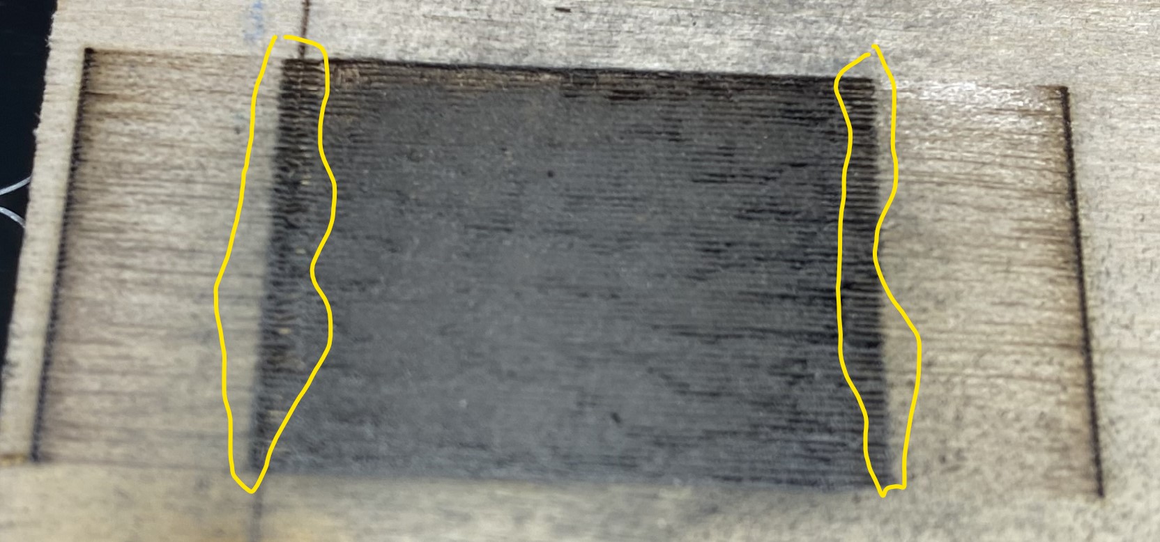
Thanks for the reply. I have read through Marten’s post with your input a number of times before today. I have incorporated much of the input from that thread and still not quite getting the correct results. Laser cuts just fine, and engraves, but has what I would call witness lines at the over scan distance.
I have looked at the scanning offset adjustments, but I do not think this would be the cause for these “witness” marks. The laser is not shutting power off completely in the Overscan part of the move. You can see in the gcode that power is set to zero with the M10Q0 line and I have an M11 command after each cut move which should be turning off laser power too…correct?
Half speed/half power produces that same results except for a shorter over scan distance because of the slower speed.
The PWM signal to the laser in UCCNC is set to 5000KHz. The Kernel Speed for the AXBB-E is set at 400KHz.
Any delays in the M3/M4 signal in UCCNC are set to zero.
At this point I think the G-code configuration is okay.
My next step is to write some simple g-code with slow speed, low power, and long travel for cut move and over scan move so I can watch what some of the outputs are doing in UCCNC, the motion controller and the Laser Adaptor control.
Usually diodes work at 1000KHz but sure this doesn’t cause the problem.
Other things to try:
Make a full square in black in an image program, save it as a bitmap and run it with the UCCNC Laser plugin. Compare the result and the code generated by the UCCNC.
Disable overscanning…
Draw a square like the one in the test add a line sub-layer and test.
Good day guys,
Unfortunately, I don’t have much to say. I only intended to do cutting with my laser, and engraving was just a remote option in case needed, but I never made it that far as I still had unresolved issues with settings to engrave. So, it’s just cutting for now.
I am not sure if the following is of any use or value to you, however, give my opinion about what I learnt, to start with, given a CNC router gantry is much heavier than that of a laser, you have to run the gantry speed heavily reduced to counteract the inertia, which for most hobbyists might be acceptable. However, the preceding situation now brings the user to operate on a very delicate and tight level of laser power control, since both speed and laser power need to be lower, I think that a router controller would have difficulties controlling laser power in the realms of 0.1%ile ranges.
Thanks two you both for the input. I turned off the over scanning and then it just burns deeper at the edges of the engrave because of the ramp down and up in speed.
I am looking at moving the laser control on the AXBB-E motion controller from non-isolated 5v outputs to using 24v Isolated outputs. These outputs have high speed 10Mbit/sec optocouplers and an N-channel Mosfet transistors.
I need to do a little bit of wire reconfiguration to do that, but I am suspecting that is the problem and not in the G code.
Here is video of it running the code. Yes high Z and lower power on purpose so i could video it. You can see the shift in brightness for the M10 Q0 but it is not zero power.