Got a 1000x600 lasercutter, Ruida was added later. Could make it move to 0-0 to end switch home position with the ruida touch panel, but Lightburn has then x=380 y=300 whatever I do.
Workspace is correct with 1000x600.
I can run the frame simulation, but this somewhere in the middle of my working field (probably around 380-300), although the object is positioned close to 0-0.
If I run “reference”, it goes to sth around 380-600 (where I can reset the position to 0-0).
With “start position”, it returns correctly to machine 0-0, but then shows 380-300.
Lightburn is on “absolute coordinates”.
When I hit “home”, it does nothing.
I can 0-0 the Ruida, but this does not transfer to Lightburn, it get’s other coordinates.
Conclusion: I cannot synchronize Lightburn and the Ruida controller. Either one does not have 0-0.
Sounds good, thank you - but which Lightburn release is that? I still have 1.7. sth, don’t remember having seen these adjustments. Is that hidden somewhere, cause that would have been obvious to change, I’m not shure I have that in my release.
Google search told me to switch the direction on the GRBL console - is this the same change as in the panel above?
“Move to the corner with the home switches
Activate both switches
Move slightly away from the switches
Tap them again and move away
Stop with XY coordinates = (0,0)”
It does that when I use the Ruida control reset, yes. But not with Lightburn. I had to change step motor direction by wiring bc they creeped to the wrong side.
Reversing that again did not help with Lightburn, that would have been logic.
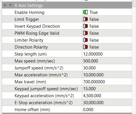
The Machine Settings moved from Edit to Laser Tools. With that open, the axis settings are under Vendor Settings at the bottom of the list. When you click the triangle to expand Vendor Settings, you’ll see a warning about wrecking your system: agree if you dare.
Ruida controllers:
Do not use G-Code
Are not based on GRBL
Do not have a console interface
Which tells you why Google searches (even without AI) cannot be trusted for detailed technical advice on obscure topics.
Good: the machine homes properly, so you need not tinker with those settings.
Now you can continue with the rest of the setup.
Changing some settings require restarting the controller before it recognizes them. This is a nuisance, but it’s the only way to be sure.
Return the wiring to its original state, then:
Change the Direction Polarity switch in the Machine Settings for that axis
Verify that the machine homes correctly when turned on
The jog arrows on the Ruida machine display should move the laser head in the indicated direction. If not, then change the Invert Keypad Direction switch for the incorrect axis. That change will (should) also make the LightBurn jog arrows in the Move window behave properly.
With those settings adjusted, the machine should home correctly, then jog as expected from both the machine display and the LightBurn Move window.
Then you can proceed to calibrate the axis motions. Ruida controllers use distance per step, rather than GRBL’s step/mm, but the process is the same.
Then set the axis speeds & accelerations to match the machine’s ability, which will require some experimentation. The values in my screenshot should be approximately right for your machine, but will certainly require adjustment.
After all that, the machine should be reasonable functional …
The machine is in the cold workshop a bit too far away now to check every advice I got here (sitting in the warm office) instantly, but I’ll do that tomorrow.
But I think the work flow is clear to me now…given I can find the hidden panels to change the directions.
Does Lightburn have a home recognition, i.e. moving to the switch spots, exactly 0-0?
Or do I have to repeat the homing with the ruida every time the steppers lose steps or to be shure about that?
On the long run, I want to change 0-0 into the corner left front bc this logic to me mathematically. This means, I need to move the switches - no problem here. I’m gonna place a mechanical stop (for the workpiece) and rulers on x and y to make the material placement easier - anything speaking against this?
This also means I need to wire the steppers correctly for the new Ruida home run direction (could not find a choice for the 0-0 position yet, seems to be standard in rear right position) and then change the Lightburn directions accordingly.
Does this change cause problems for later if I want to use a conveyor function (for cloth/foils)?
No, because as @jkwilborn pointed out, LightBurn cannot tell the controller to perform a home operation. The go-to-home button in the Move window sends the laser head where the controller thinks that coordinate is.
However …
If the machine is losing steps, then it is not configured correctly or it is crashing the laser head into obstacles on the platform that should not be there. When that happens, the controller does not know where the laser head is, so you must home the machine again.
Basically, you must fix the real problem, not work around it.
With a Ruida controller, you do not have that choice. The origin must be in the corner with the home switches and the machine must home to that corner.
My machine homes to the rear-right corner, so the X coordinates increase leftward and the Y coordinates increase frontward: it’s like that and that’s the way it is.
You could move the home switches to the front-left corner and twiddle the homing setup to make that work properly, after which the coordinates would behave like a piece of graph paper. On my machine, that would require mechanical surgery and a distinct loss of workspace, because it has no room for those switches in that corner.
While (some) Ruida controllers have provision for a conveyor function, it is (to put it mildly) lightly documented. To the best of my knowledge, nobody attempting that has lived to tell the tale.
Bonus: because Ruida controllers do not have a programmable user interface and do not use G-Code, there is no way to inject commands into the job as one might do with custom G-Code on a CNC controller.
The most simple way is to make a jig for you laser that will hold the material in the correct place.
There are three options to tell the Ruida where to return. Absolute, User and Current. I use absolute when I do jigs, but otherwise use user origin. User origin (ORIGIN) is set on the console and the return location is set in the machine settings.
@ednisley is correct in that it’s difficult to change origins. Remember the Ruida only works with positive numbers, you the home operation tells it which quadrant it’s operating.
I’ve tried to help at least one other person change it to a different quadrant, but was unsuccessful. They ended up contacting MW Laser (down under) and paid for assistance to get it working. They claim it took a while for them to work it out.
Unless you’re using numbers, it shouldn’t matter where the origin is.
Uh, one more thing came up: the honeycomb. I assume it’s not advisable to cut through sth which lies on the frame, i.e. not on the honeycombs?
Then my cutting area is not 1000x600, but max. 960x620mm which annoys me a bit. Are there larger honeycombs available?
The question is if: can I place the 0,0 on the frame, which affects the desired new position of the switches.
I’d rather get a larger honeycomb and place the switches now to the mechanical maximum instead of the restricted honecomb (frame width 20mm all around).
Any alternatives to the standard honeycomb, like stretch metal? The problem will be the build up of molten material, I guess?
Kind of lost me here, I don’t understand what you mean. Mine has trianglular aluminum bars to rest the honeycomb. I took those out when I put in the metal plate.
I found the honeycomb didn’t work for me. The air went down the honeycomb instead of over the material.
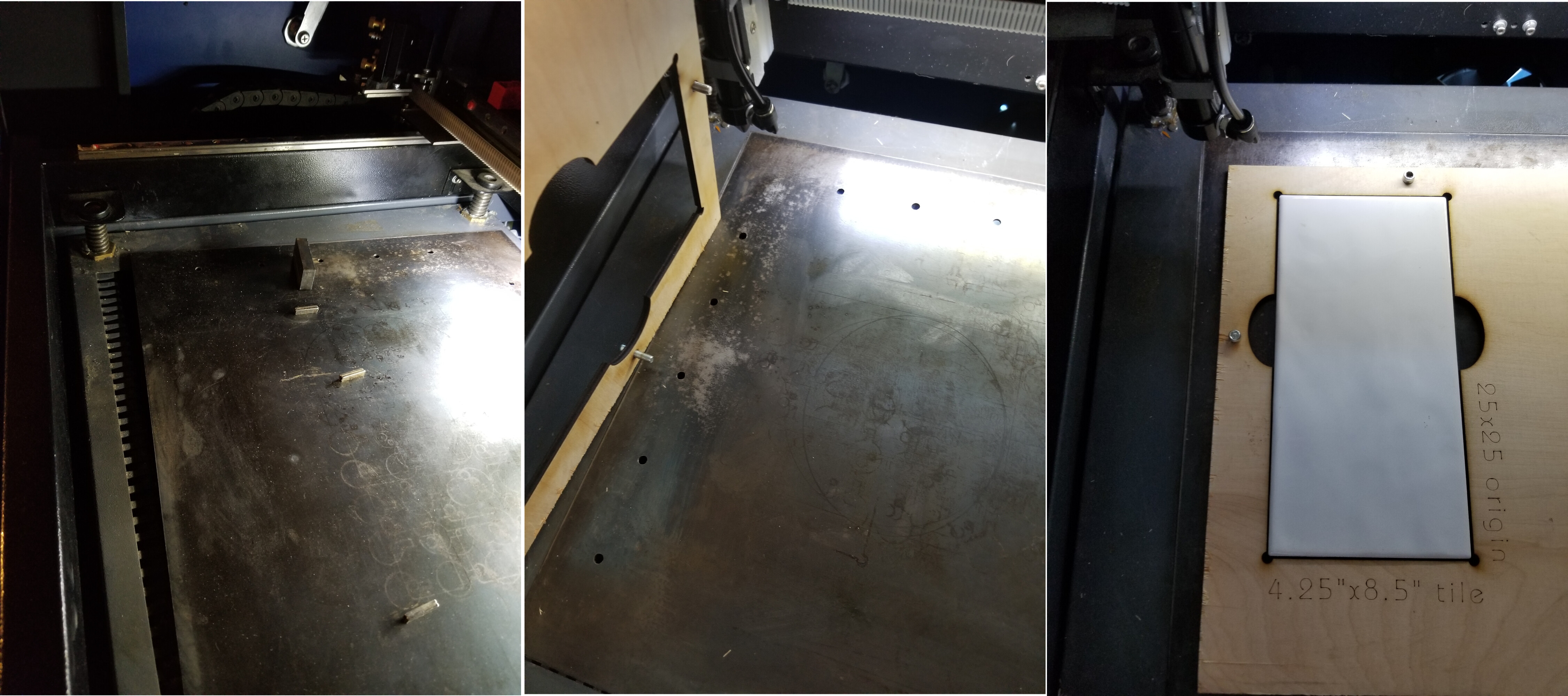
I put a sheet of steel in mine and drilled locating holes for jigs. The plate wipes off pretty easy and isn’t damaged if struck by the laser.
This is 5mm sub flooring cut at 45mm/s@45% with my original 43W tube. The machine ventilation and air assist is the stock, the lid is fully open. The sheet of steel was cut by one of the steel suppliers near me and cost $12 USD. Had it in use for close to 6 years.
You should be able to move them outward, not to a different origin relatively speaking. If it homes to the upper left you can change these around as long as it still homes to the upper left.
Ensure you head passes over all the components. Mine is s 5030 (500x300mm), with the new head it now will let me go to 540 along X. I have a choice between it being wider (X axes) or more depth (Y axes).
The head runs into the Z adjustment if I go for maximum size. Sorry I don’t have a photo.
Aha! Mine has a U shaped frame, so I lose 20mm each side. I must see if I can reduce that to enlarge the real working space. Perhaps with cutting off one arm.
Stupid enough, the resting frame with the z mechanics is larger, so mechanically I could cut at least 1000x650…but the honeycomb isn’t. I could change the sizes in Lightburn.
How is your honeycomb then fixed on the triangle? Glue?
You can move the controller’s origin point inward by changing the Home Offset value for each axis, without moving the switches.
The controller automatically moves away from the switch until it releases, then defines that position as “home” with the coordinate 0.0, so the Home Offset adds more distance.
I must’a got the deelux version, because the honeycomb frame has a pair of crudely drilled holes for M4 screws into the platform:
The frame holes aren’t perpendicular and don’t quite align with the holes tapped in the platform, but finessing the screws down locks the honeycomb in place.
Mine isn’t locked at all. didn’t bother me yet bc the material isn’t locked either, so if there’s a collision it will be displaced anyway.
But I will see to that as soon as I decided the 0,0 position bc I want a mechanical stop for the material to have a repeatable workflow and reliable orientation.