I recently converted from Leetro/Lasercut 5.3 to Ruida6445g/Lightburn. It was difficult to interpret the nomenclature between the old settings and the new. Regardless of that, I have almost all working now but I do have an issue now.
I imported a dxf from my cad software. This contains a rectangle box with text in the middle.
This has 2 layers. 1 for engraving first and 1 for the cutout.
When I push the radio button to show the job boundary, all is good. It’s about a 3"x1" rectangle,
When I press the radio “Start” button it starts the engraving layer but the problem is this:
It travels negatively in the X-Axis for about 12", travels to the right and engraves the 3" section, continues past for another 12" (without firing), and repeats this for the engraving.
After the engraving is done it will activate the cutout layer and cut the part out as it should without any excessive movements.
Normally I would change one thing at a time when changing settings but this time I changed a bunch. Mainly when I cut this part out prior to all this, the text was not at a sharp 90 degree vertical walls. It was like the firing of the laser was delayed maybe causing a not so crisp text.
I thought this could be due to my accelerations or ramping. After making all those changes and wanting to cut the part out, I have what I have now.
My biggest question is, would changing the ramping and accelerations make the laser travel excessively in both directions to perform engraving tasks? Maybe with my settings, it now needs more travel area to start the engraving? I reduced the setting drastically hoping that it was an acceleration/ramping issue that caused my text to not look so good.
Any suggestions would be appreciated.
My Machine:
G.Weike LC1290
Ruida 6445g controller
100W Reci Laser with 2" focal length
Lightburn Software
Vectric Software for Cad
Lower acceleration means a longer ramp up/down time on either side of raster engraving, yes.
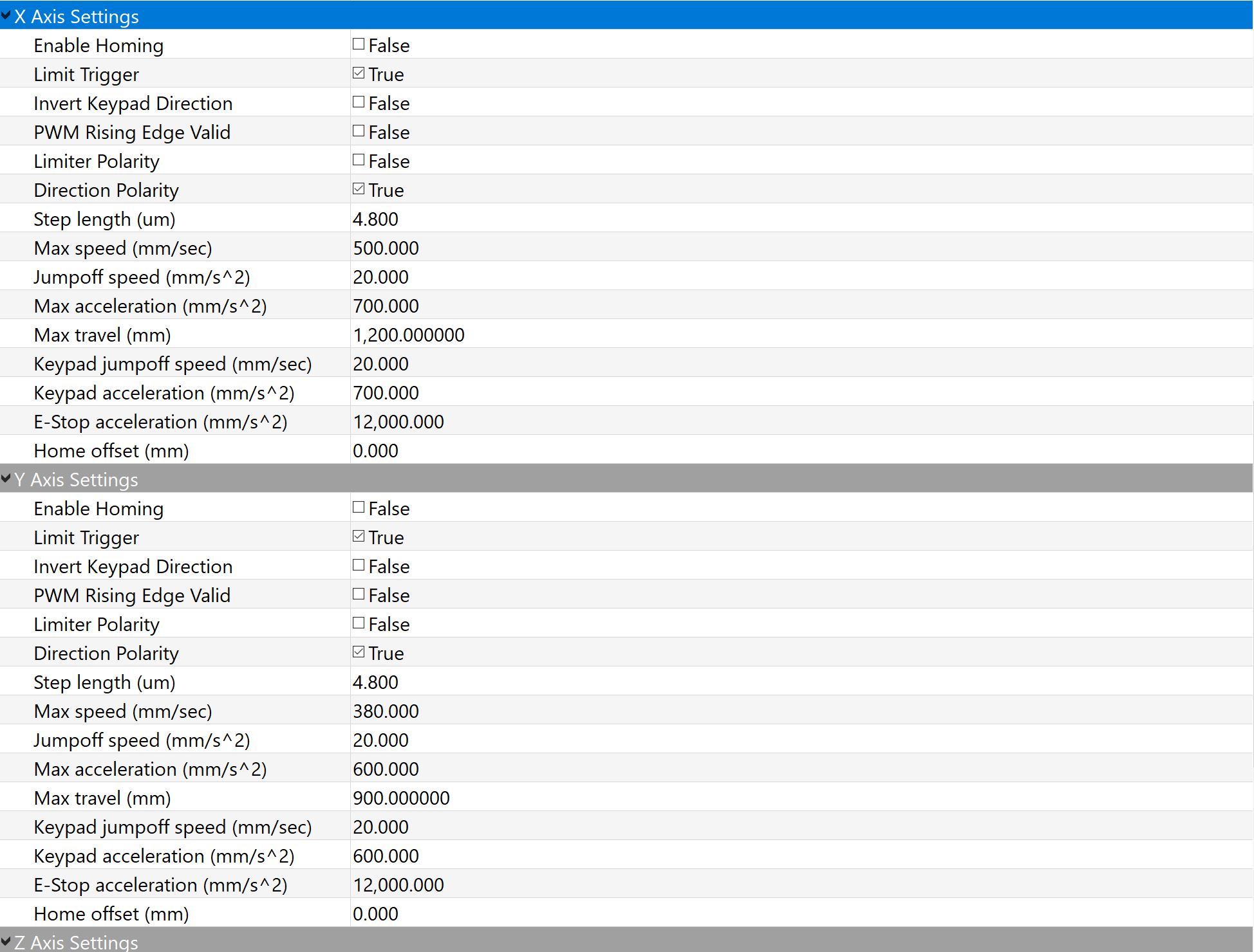
Your acceleration parameters are very low. You haven’t specified the speed you were trying to engrave at, but if it was 350 mm/sec, you would need 1/2 second to accelerate to full speed, and the head would travel 87mm in that time. If you tried to engrave at 500mm/sec, you would need 0.715 sec, and the head would travel 178mm on either side, and this is assuming these numbers aren’t scaled by anything else, which they might be. (like the 80% accel factor)
My settings on my red/black 700x500 machine were roughly 10x what yours are for acceleration (7500mm/sec^2 in X, 5000 mm/sec^2 in Y, and the max values in the vendor settings were around 10,000).
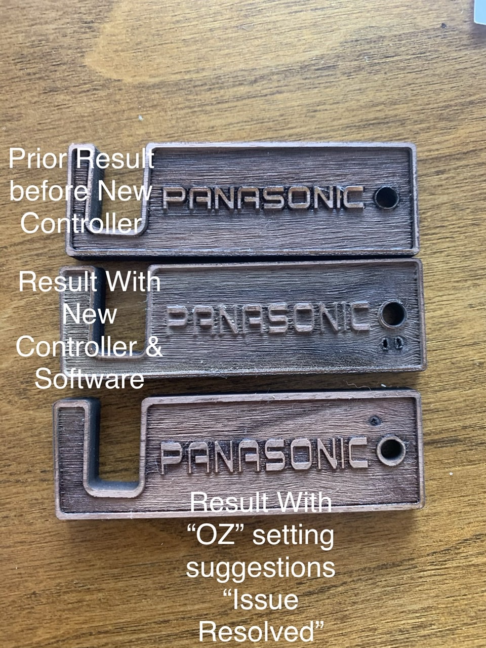
You haven’t described the issue you were having with text very well. Can you elaborate or show pictures of what was happening?
Looking at the picture I do understand that it is two different files. I didn’t realize the difference in the two and I must of selected the incorrect one. That doesn’t change the outcome though.
Looking at the picture you can see that the border walls are not consistent and the text almost has a blurring affect as well. The top sample was right before the conversion and the bottom is with the conversion.
When I did change those setting I too noticed that they were way slower than previously.
Have you run any simple tests to dial things in? Square, circle, etc - A common check is to run a square or circle of known size as an engraving, and then do another one where you follow it with a vector outline to make sure they line up. Measure the result to make sure the step sizes are correct, and that the output is equal in both directions (square).
Thanks again for your response and suggestion. Thank you for confirming my suspicions and what was happening. All the excessive travel has been eliminated for obvious reasons. The resulting cut out is about 90% perfect. The other 10% is fine tuning.
Are used your settings as a baseline and my machine was just as happy. The resulting outcome was exactly what I was getting from my previous controller.
No I haven’t ran those test. I did perform a line test on both axes and measured with calipers traveling 6 inches. Those were spot on. However, what you just said makes sense to make sure that they lineup. I will perform the circle square test engraving followed by a profile cut to confirm that both are in sync.
Scanning (engraved fill) tests will sometimes slant to one side, which can indicate incorrect polarity of the motor step pulses, so that’s a worthwhile one to check.