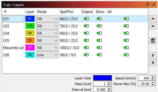
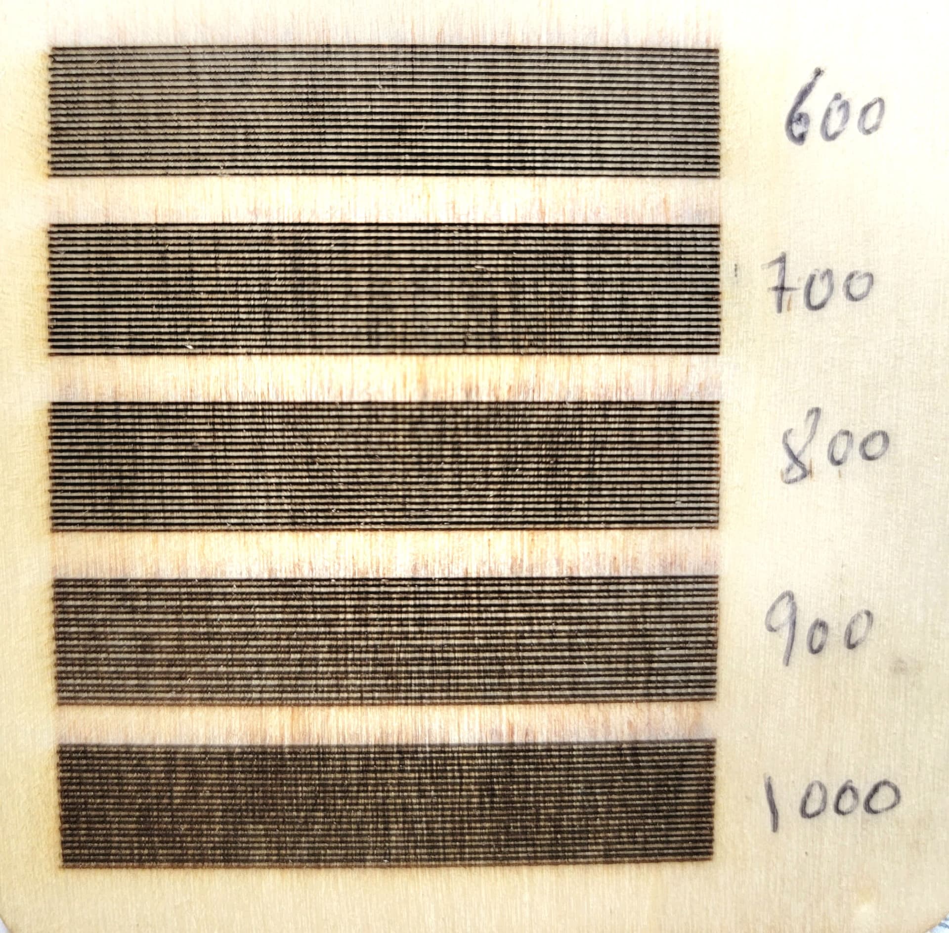
I was reading in Lightburn documents about scanning offset adjustment. I followed the instructions as much as I understood them, but I am not sure exactly of what should be done. I ran the test, and I can see a shift on the left side of the fill. I ran it at lower speeds, (600 through 1000) at a 100mm/min intervals. The instructions says to put the overscanning at 5% and the line interval at 0.5. After the test I measured the offset distance between the lines and recorded it in the “Scanning offset adjustment” in the device settings. Also the instructions mentioned to put only have the value of the offset. I attached couple photos and I need to know if I did this right. Also, should I have the Initial offset value at zero?
Sorry for the long story and I appreciate the help.
The 600 mm/min value seems odd, as the lines still look offset, but only on one end. Was Bidirectional fill turned On so successive lines are scanned in opposite directions?
The line shifts generally get higher as the speed increases, due to delays in the controller → laser electronics, so:
Turn the adjustment switch Off
Turn the Bidirectional fill switch On for each layer
Run the test blocks at 100 300 1000 3000 10000 mm/min (*) with power levels as needed
(*) Or whatever the machine’s maximum speed might be
Then measure the results, divide by two, and fill in the table again. Upload before-and-after pictures here, so everybody can admire them.
The Initial Offset value slides the whole line to match delays in the motor vs. beam paths, but generally isn’t needed.