Hello everyone and sorry for bothering you IF this topic has already been solved somewhere else
I’ve been struggling for 3 hours looking for a solution to my not-effective rotary setup into Lightburn
I’ve been looking to MAAAAANY posts here but nobody goes to the exact point where my problem shows up
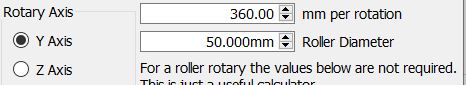
I setup EVERYTHING about the rotary in Lightburn, but ANY changes (mm x rotation, roller diameter, etc…) don’t make any change in the final rotary behaviour
I attached the Y axis’ cable to the rotary as it is meant to be done, the rotary works 100%, reversing output works, but NONE of other changes seem to be written (or modify) the inner GRBL values
Please HELP 'cuz I was close at throwing the rotary out of the window (5th floor)
What parameters are you expecting to see changed in the controller. I have not played with my new rotary that I bought with my new machine, but I believe those numbers you put in the Rotary Setup window are used by Lightburn to calculate the path.
What does not happen? There are lots of rotaries out thereon a variety of machines, all doing mugs and glasses. Can you tell us what you are not seeing with your system?
Then this is one the @JohnJohn Lightburn team might want to investigate. But I am suspicious it had something to do with your installation and not Lightburn.
Which engraver are you using with your Rotary? It looks like it’s the Atomstack X20.
You connect the rotary to the Y-axis… Is it safe to assume you unplug the Y-axis motor and plug the motor for the rotary into the motor end of that cable?
Does the motor just sit and vibrate when you’re expecting it to move? If the Y-axis motor and the motor in the rotary aren’t wired identically, this can be the expected behavior. The easiest way to confirm this is to test the disconnected motors with a continuity meter. There are two windings in the stepper motors used for these engravers. They’re often named A & B. Each winding has two ends. In the 4 pin edge connector, the ends of the windings either alternate A+, B+, A-, B- or they’re side by side A+, A-, B+, B-. If you don’t have this symptom, it’s not this.
Is the Rotary a Chuck-Type or a Roller Type?
I’m guessing this is the Atomstack X20 because of this comment about GRBL values. I also think you’re talking about ‘Machine Settings’. Some GRBL-controlled engravers have a manufacturer setting that won’t allow their settings to be changed. Most manufacturers move away from locking up the firmware settings in newer versions. We can check and test this.
When you first Connect to your Atomstack, the welcome message contains the firmware revision number and build date. Please select and copy the text from the Console window in LightBurn and paste that information into a reply here.
The best way to confirm changes to the motion commands is to click File, click Save GCode, and save that file somewhere convenient. Change the state of the Rotary in the window then click File, click Save GCode, and compare the two files.
Please respond if any of this helps you get unstuck… Or if you’re still stuck.
So, first of al THANK YOU for the help, I REALLY appreciate it so much 'cuz I’m hard stuck in this situation.
The laser is exactly an X20 (awesome guess) an the rotary is a roller
I unplug / plug the Y axis motor wire from motor to roller
the rotary seems to work flowlessly, smooth and precise, point is that its movement is ALWAYS constant, none of the changes on “rotary setup” parameters in LB do affect roller’s behaviour, it ALWAYS rotates by the same amount of degrees like there’s no compensation of the given object circumference
these are the requested infos from console
[VER:1.1h.2022070601:]
[OPT:VZ,15,128]
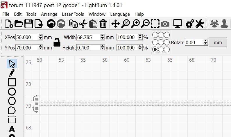
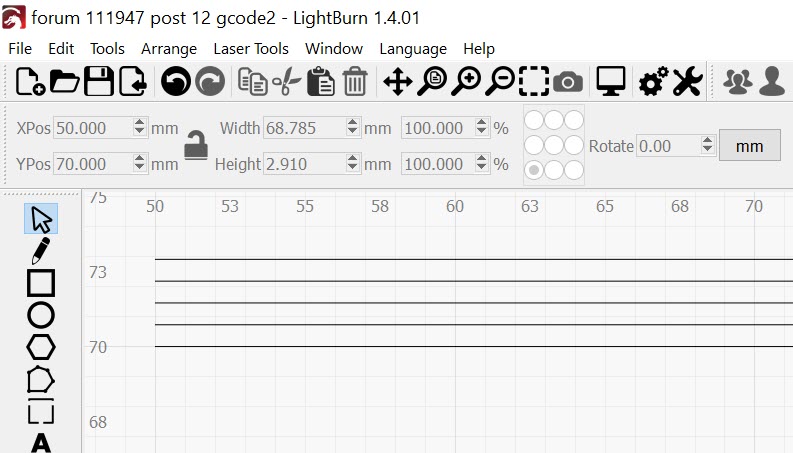
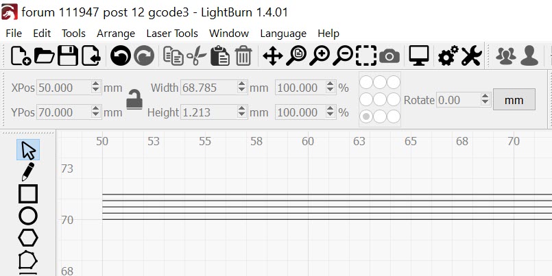
Here are 3 Gcodes, I didn’t attach the rotary (I think it doesn’t affect at all):
Fortunately for me, LightBurn has a GCode importer.
I copied the ‘Normal’ code into a text file, changed the file extension from .txt to .gcode, then clicked File, then Import. I also moved each starting point to 50mm over and 70mm up so they would all have a start point in common.