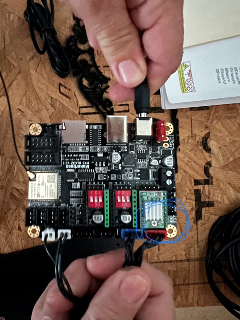
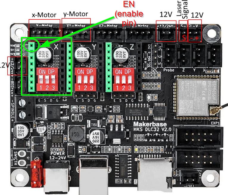
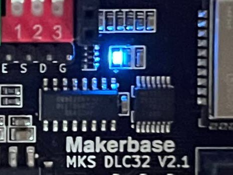
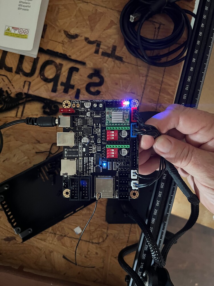
HI…I had to replace my Atomstack A5 Laserbox v1.0 with a new Makerbase MKS DLC32 control board. The pins on the Laserbox are different from the pins on the Makerbase. Laserbox came with 2 2-pins and Makerbase has 1 2-pin and 1 3-pin. I improvised and connected it the way it was recommended on a hardware board on here. My question is is what do the lights mean when they light up on the board? In this picture the light is not lit but I circled where the light is. It is blinking blue. Please forgive my ignorance as I am just a beginner with a laser.
Thank you for any information you can provide. I dont want to fry another board.
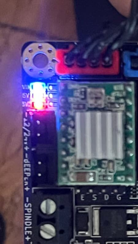
ok…so I changed around the wires and now the lights no longer blink blue but the vin light is solid blue and the 5v is orange and the next one is red. The light in the middle of the board is now lit and blue .

1 Like
Don’t know this board but solid lights usually indicate power and blinking indicate data activity.
1 Like
There’s a wiring manual for a DLC32 v2 board here - it may help.
I appreciate the information and I have just one more question. when you have a two pin with one wire and a two pin with 2 wires where would you plug them. They are all coming from the laser to the control board. Right now I have the two pin 1wire plugged into the 12v+ and the two pin 2 wire plugged into the S TTL. Would this be correct?
What is your pinout say on your laser?
Please forgive me. When you say pinout what do you mean? Just an old lady who hasn’t a clue.
Thank you for reply
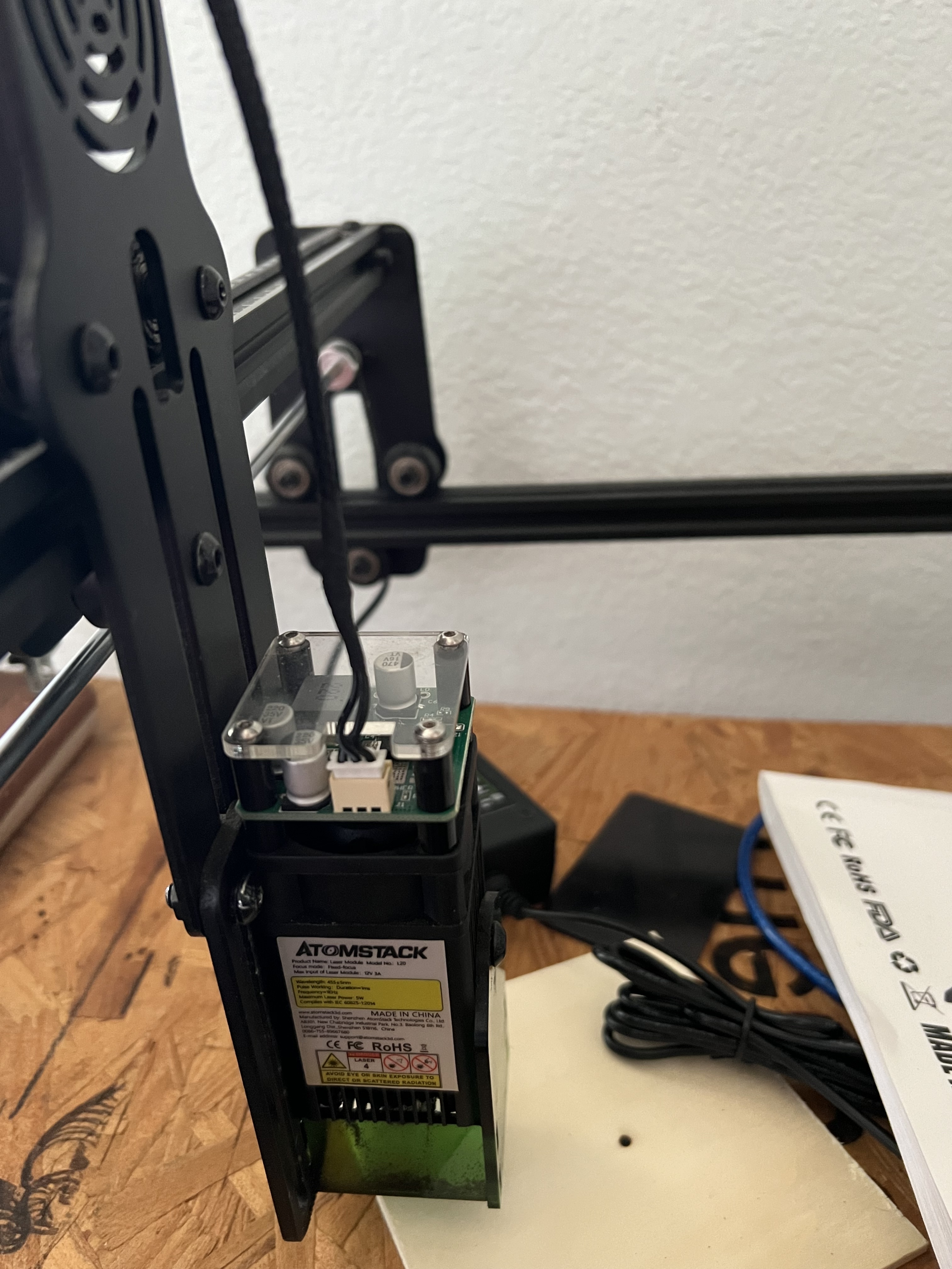
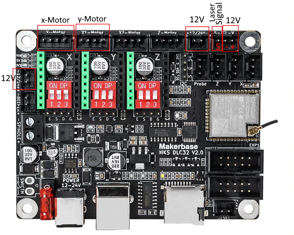
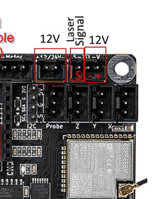
Nearly, I guess. See the picture below. Put the two-pin/two-cable connector into the two-pin 12V socket. You can connect the two-pin/single-cable connector to the three-pin socket, but make sure the cable sits to the leftmost pin. If not, change the plug.
It could look like this. (There is an adaptor cable that takes the pin from the signal cable and mounts it to the board)
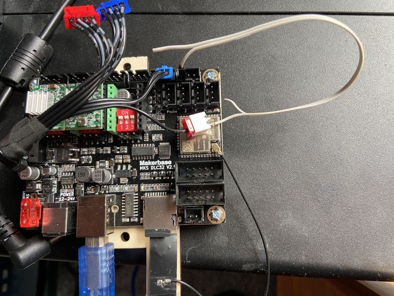
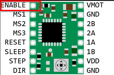
And another thing: make sure the stepper driver is correctly inserted. If you look closely at the boards, there is an enable pin (EN) marked on each. Those need to match! Otherwise the board will be damaged. It’s difficult to read on your images, but I think yours is inserted incorrectly! Make sure to check this before powering up!
When I connected everything and changed the steppers now the light is blinking blue. Is this correct or incorrect?
Thank you
The top three LEDs (VIN, 5V, 3.3V?) Those should be on continuously. There is only flashing at the TX/RX leds for the serial connection while data is transferred.
Fortunately, It’s open source and published.
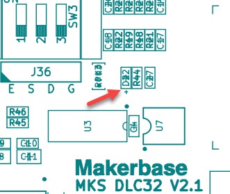
Here’s the corner of the board you’re working on.
Here’s the layout:
Here’s the corner of the layout with the part numbers:
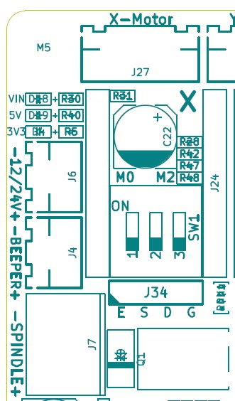
Under those Lights should be the numbers
VIN D#8, 5V D#9, 3V3 D#4 (I think. It’s next to R6 so that’s a great clue.)
Wiring diagram:
3rd page down. (click download Raw to get the whole PDF)
Looking at the 3rd page down, I see the power indicators.
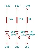
Here are the new Build part numbers:
+12V R30 D18 (Blue)
+5V R40 D19 (Green)?
+3V3 R5 D4 (Red)
The Bill of Materials isn’t published.
But Page 3 offers what we need.
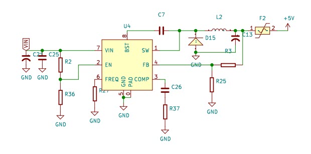
+12V enters on J1 and goes through Fuse 1 and some noise suppression capacitors and back EMF diodes.

VIN enters U4 directly inboard of the J1 power jack. U4 is an MP1584EN which is a high-efficiency down converter that makes 5V at 3 Amps.
https://www.monolithicpower.com/en/documentview/productdocument/index/version/2/document_type/Datasheet/lang/en/sku/MP1584EN-LF-Z/document_id/204/
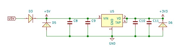
5V enters U5 and comes out as 3V3 (Shorthand for 3.3V)
U5 is marked ON semiconductor RPF 17.33
It’s a 3.3V voltage regulator. 1.5 Amps (max)
https://www.onsemi.com/pdf/datasheet/ncp1117-d.pdf
Mine are all steady and not blinking.
If yours are blinking, I’d be concerned that you may have an overload situation and may be bouncing off the current limitations of the regulators.
If your VIN is blinking it’s probably best to replace the power supply with a better brick.
This one:
Back to the layout
Diode something 2… and R44 is a great clue.
back to the schematic.
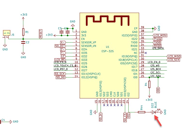
So, IO2 goes to:
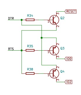
DTR = Data Terminal Ready : RTS= Request to Send,
On Page 4 These go into U6 (CH340 Chip) along with the data lines from the ESP32 then out through D+ and D-. Those data lines go to the USB Port J8 (also on page 4).
(fun deep-dive… thanks!)
1 Like
When I had the wires reversed from what the gentleman told me earlier, I had all three lights solid and then when I reversed wires to what he recommended, I have one blinking blue light.
Before wire reversal
So to simplify, the three lights in the corner should be solid and the one in the middle should flash at no fixed interval or rate.
Is this wired correctly?
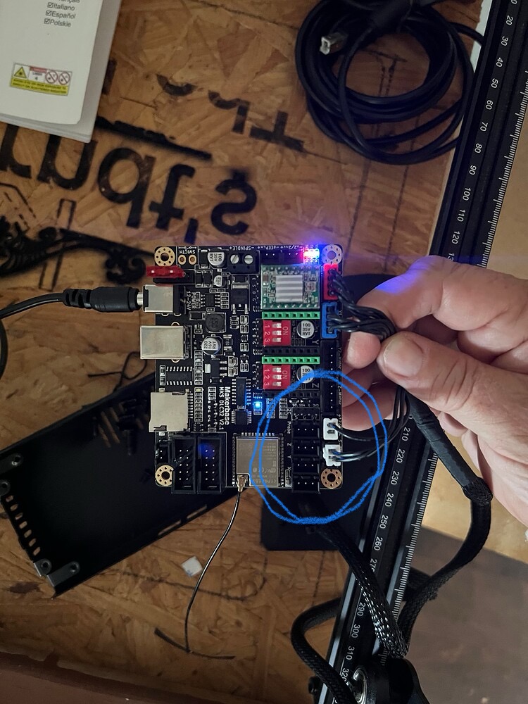
I have 2wire 2-pin in the +12/24- and 1 wire in the S slot of the S-TTL-VIN
That is correct, but your picture shows it differently. ![]() According to the picture you have a single wire in the 12V port and two wires in the S-TTl-V Port.
According to the picture you have a single wire in the 12V port and two wires in the S-TTl-V Port.
1 Like
Your single wire should be plugged into the 3rd pin from the corner.
Yes. Correct. The lights are lit and not blinking when I have in this position but when I change to the 1wire 2-pin to the S position only one light is lit and blinking. I’m sorry to be asking so many questions. I just play around with my laser and am not schooled on all the ins and outs.
Ok. When in this position 1light blinks blue. Should it be doing this.
As @misken pointed out, the pictures in this post, that post, and the most recent post, show that the stepper driver board is inserted backwards, which is pretty much guaranteed to damage either the driver or the microcontroller board.
Because the destruction is instantaneous, you should assume either (or both) boards are kaput.
At this point, discussions of the meaning of various indicator LEDs may be irrelevant.
Source: Been there, done that. ![]()