Y-axis next to the controller (front or lower side) and one on the x-gantry on the right side (above the LCD)
Both switches are working as I get a message on the LCD when pressing either one of them.
But when using the homing sequence in Lightburn the motors start to move in the right direction (lower right corner) - but they keep running even after the end stops have been reached.
ALARM:1 Hard limit triggered. Machine position is likely lost due to sudden and immediate halt. Re-homing is highly recommended.
Very good point. I’ve checked and yes, they do reach. The console prints out the Alarm and the display pops up with that message. So my reasoning is, that both the machine and lightburn realise that the switches have been hit.
It’s just that the motors aren’t stopped.
I had assumed, that it would work like a 3D printer, where it back up and slowly comes back to calibrate that end.
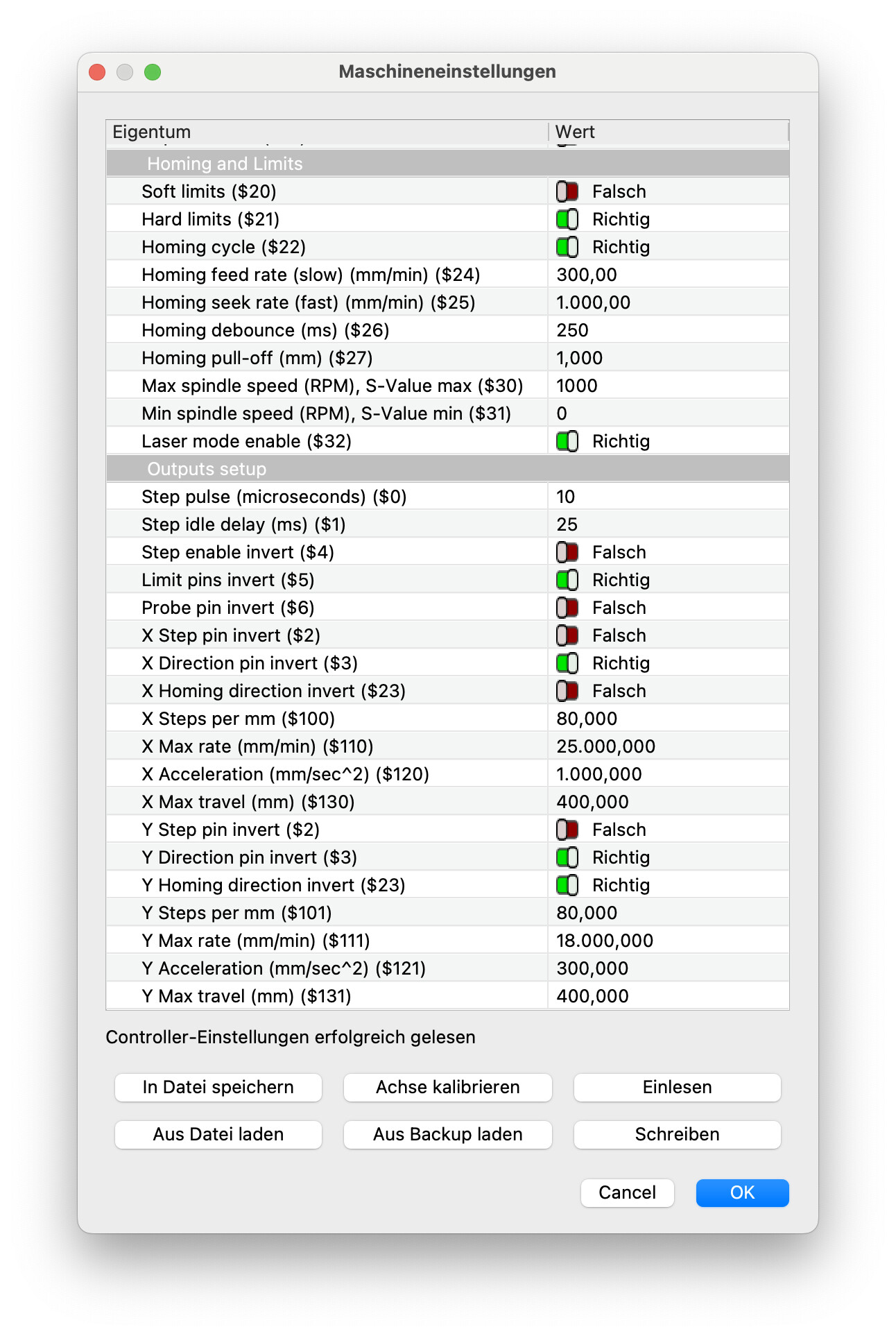
I am reluctant to have you change $5 (yours is set to the typical value) because your controller input pin may not be wired properly for this setting. I suspect, because it is a DIY project, that you may have the switches wired improperly to the controller. Just because you see actuation results on the LCD panel does not mean that actuation is in the right direction.
Please review this link previously posted, triple check your setup, and then come back if you have questions or it is still not Homing properly.
P.S. Put a copy of those GRBL parameters in a safe place!
I figured it out. Thanks to your suggested wiki!
probing the switches open with “?” got me: <Idle|MPos:0.000,0.000,0.000|WPos:0.000,0.000,0.000|FS:0,0|Pn:P|DISCON>
Touching the x-switch got me: <Idle|MPos:0.000,0.000,0.000|WPos:0.000,0.000,0.000|FS:0,0|Pn:PY|DISCON>
I had them connected, but they were switched around. So when I was homing and the first switch was hit the other motor stopped turning, but the one that was supposed to stop didn’t.
Makes perfect sense, now that I figured it out. What a stupid mistake on my part.