Hi all,
I am going to do my best to describe my issue and hope someone can help.
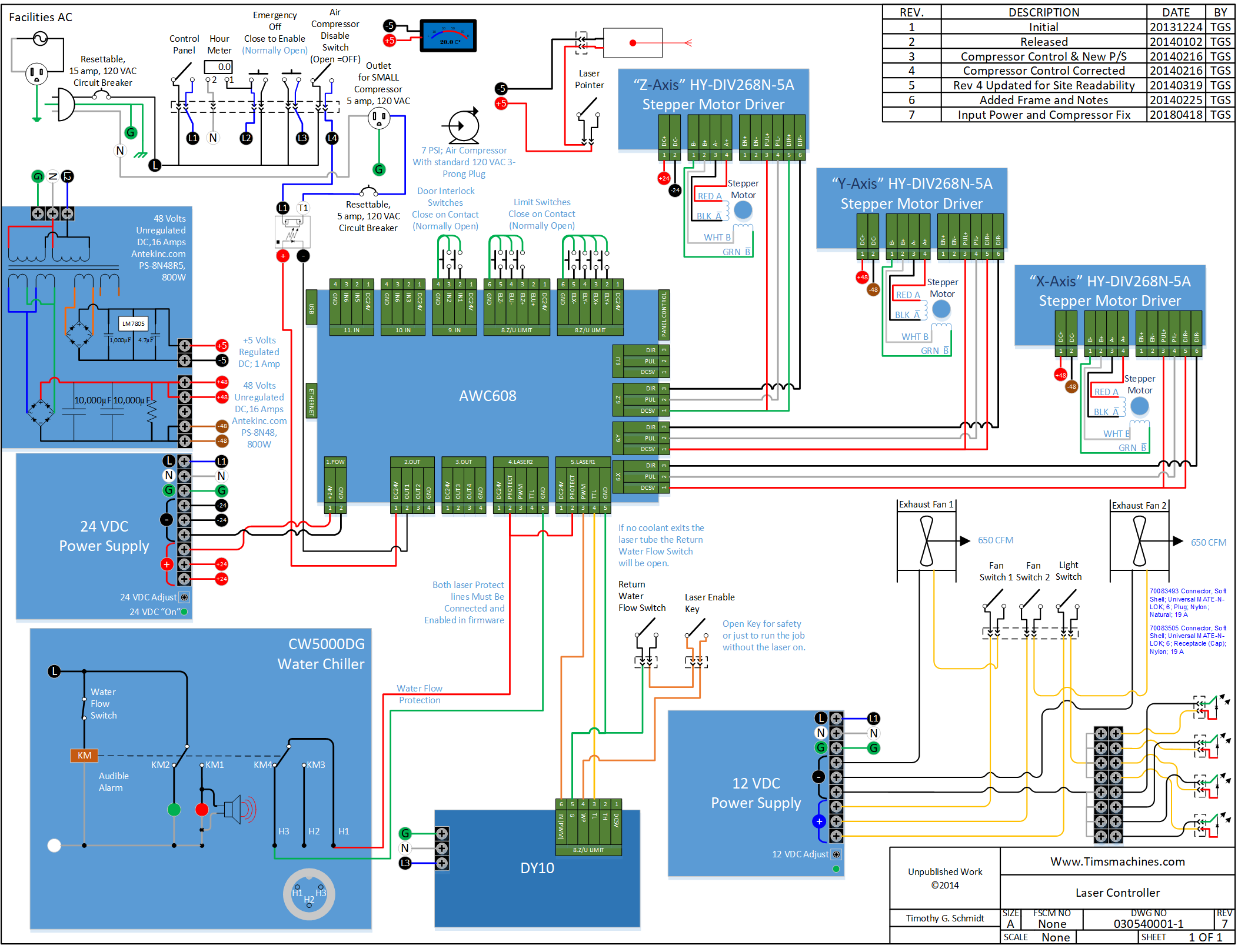
I bought a new Chinese laser cutter with a 600 x 400 cutting area. I had an Anywells 608C controller in a K40 and transplanted that into the new laser.
When I boot the laser the head homes to the top left corner and keeps going. I obviously don’t let the motors keep running so I unplug them.
Once the control panel is initialised I can attach the plugs to the stepper motor controllers.
If I home the laser it will run and run and run unless I press stop, however, if I use the controller to try to move past the x and y limits at the top left corner the limit switches stop the movement. If I also try to move the head to the bottom right it will stop somewhere near the mid part of the table.
If I move to the top left I can set an origin point at the home position it works fine. I can also read the machine settings and the head will move to the bottom corner but still if I press home the machine tries to travel past the x and y limits at the top right corner.
I feel that the home position in the machine is set off to the left and up from its actual position and its trying to home there. I have looked at “Configuring a Ruida” but there is nothing about setting home in the machine.
Can anyone suggest why this is happening and if there is a specific fix anyone can suggest?
Thank you so much for looking.
MinkiSan
Has this ever worked since the controller upgrade?
You can’t set ‘home’ it must initialize to it’s home position at least on DSP type controllers. There is an origin, but it’s pretty useless if it doesn’t home properly.
Are your limit switches electronic or mechanical?
Are the set for positive or negative (NO or NC) configuration?
It is not homing, so it’s confused. Limit switches work very simply.
I think this has given me something to think about. My brother is the person who actually did the transplant and without documentation so followed what he thought was right. If you are familiar with the controller he has not wired pins:
(4 gnd to pin 3 in2 and pin 2 in1 on 9. IN) and neither has he wired either of the (8.Z/U LIMIT) blocks.
If that is a Ruida controller, you can swap the polarity in the Vendor Settings to reverse the motor direction. You can check the limit switch activation in the diagnostic page on the controller.
