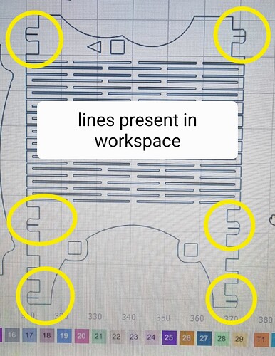
Hi, new to the hobby & still finding my way around but learning quickly. I hope someone with more knowledge can help me in the right direction. I have been working on improving the fit of my box joints by adjusting the kerf offset which has worked very well. However I’ve just obtained a file i wish to cut but when i preview before cutting i noticed several lines were omitted where a small relief cut is made. I wondered if the kerf offset could have caused this and dropped it back to zero. Now in preview the missing lines are present again. Im probably missing something obvious due to my lack of knowledge but if i cut the pieces with my kerf offset removed then i will encounter tolerance issues. This is on Windows 10 using a Neje 3 pro Grbl. I would very much appreciate any guidance that can be given.
Can’t tell from the screenshots but I assume that’s a slot within a closed shape.
In that case, what would you expect to happen to that area when applying a kerf? What should happen to it?
I assume what’s happening is that the kerf is intruding into the adjacent space thus essentially erasing it.
Thank you for replying, yes there relief slots to allow movement when fitting together. So essentially i need to make those lines a different layer and not apply kerf offset to them then? Apologies I’m still learning to walk with all this.
I think starting with an understanding of how kerf adjustment is applied will help you with it.
Kerf adjustment is no different than applying an offset of the same size, outside or inside depending on positive or negative adjustment.
So you could potentially make the relief shape bigger or apply the relief cut separately from the other portions. That can get a little tricky if you apply kerf to one layer and not the other.
On a separate note, how have you calculated the kerf adjustments? Normally this would be the size of the measured kerf divided by 2.
I see now how the kerf offset cancelled out the line as its a slot in a solid shape. I set the kerf offset to reduce tolerances on my box joints. The only way i can see of correcting this it to have those slots in a seperate layer without the offset? I worked out my offset following a tutorial, making 20 parallel cuts and measuring the amount of material removed & divided that by 2. The neje module i have has a very small focal point of about 0.16mm, i found an outward offset of .07mm in light burn gave my finger joints a good tight fit. Any advice is welcome if I’m getting this wrong.
Yeah. This is fine. Sounds like you have a good handle there.
I think you have it. I’d encourage you to experiment with it as different techniques have different pros and cons. You may want to work with some test or scrap material before while you’re working through it.
Thank you for confirming im on the right track. Back to the drawing board for me ![]()
This topic was automatically closed 30 days after the last reply. New replies are no longer allowed.


