I’m throwing this out there in this category because hopefully someone can help and this is the most read category.
Hopefully someone out there has a Longer Ray5 and added limit switches and it’s working properly. I installed the limit switches and I received the cable and hooked things up to the laser module, switches, and the controller board - connecting the Y cable to Y1 - as per the instructions for installing limit switches provided by Longer. Because I have a MacBook - I borrowed my neighbor’s Windows laptop and updated the firmware and the dlc text file. I then received an email from Longer that I’m supposed to connect the Y cable at the controller into Y2 – not Y1. Anyone know this for sure? If you have a Longer Ray5 running with limit switches and it’s working properly, did you connect your cable on the controller to Y1 or Y2? Thank you anyone who can help.
This costs them money, and I’d assume they know what they are talking about…
There are many wrong documents out there by manufacturers… these didn’t get caught and ended up in the users hands… after they receive enough queries they probably email everyone and advise them of the error…
I don’t know for sure, but most of these just pull the input on the controller low…
Thanks for the reply. Other people on other forums have replied that the Y1 and Y2 ports on a Grbl controller output exactly the same information data - so according to them, it shouldn’t matter which port the wire gets connected to. The only thing I can think of is that there maybe a possible firmware change on their controller that requires the Y2 connector. I sent another reply to the support people wanting to know why it had to be on that port, as opposed to the one in the instructions. I expect to hear Monday or so. Thanks again for your input. Have a great weekend.
I’ve seen separate stepper motor driver outputs on several boards labelled Y1 and Y2. These are usually set up and installed as mirrored images of each other. Occasionally these two motors are connected by a common shaft. This creates a dual-motor drive to move in the Y-direction and to push the heavier gantry around.
A motor can be reversed by reversing one pair of wires going to the motor. It can also be reversed in the software at two (maybe three) levels; (Build time / firmware default and Machine Settings). If the Manufacturer suggested that you use Y2 instead of Y1, the firmware, motors and cables are likely well known and standard enough to suggest that this reversal is needed.
The the Limit switch instructions show to use ‘Probe’ (Pr) for the Y axis limit switch. Probe is usually vertical (Z-Axis) and usually for 3D Printing (Or cnc… )
I only see two stepper drivers on each board - something else is going on.
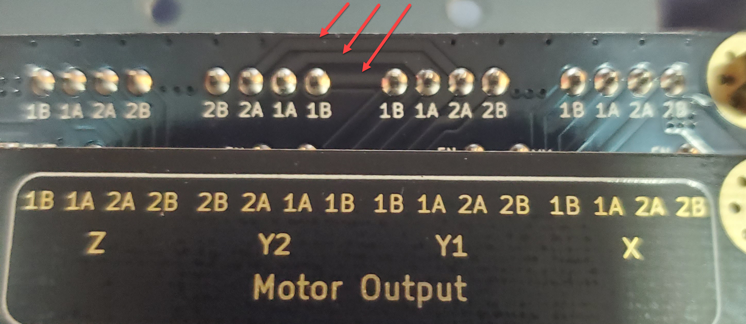
Below is a Pic. of an MKS DLC32 v 2.1.
Sorry for the glare on the ends but I wanted to catch a highlight on the top edge of the board where the circuit board traces are.
You can barely see through the solder mask, but there are three foils between Y1 and Y2. The pairs, 1B, 1A and 2A are connected, and they’re mirror images of each other - powered by the same driver chip.
When the stepper motor cable is moved from Y1 to Y2 the motor reverses. I imagine you’d see the same thing on the back of your board.
xtool RA2 Pro seems to work just fine. I just have to figure out how to really use it, still having trouble how to use coordinates [user original, current position, absolute] with this rotary chuck laser. I’m still all screwed up with the coordinates - telling me cut areas that are out of bounds and yada yada yada - still have to figure out all the intricacies of using a rotary laser, especially with the chuck… which
i may be using exclusively. Going to have to check out some YouTube videos and the Lightburn information on how to use it fully. Appreciate the feedback.
First, the chuck is a round table… on my machine I remove the Y axes motor driver and plug my rotary into it… if the table needs to move 0.10mm, then it rotates the object 0.10mm… the rotary is just a way to make a table round…
If start from is set to absolute coordinate, where ever you put the artwork on your work area is where the laser will put it…
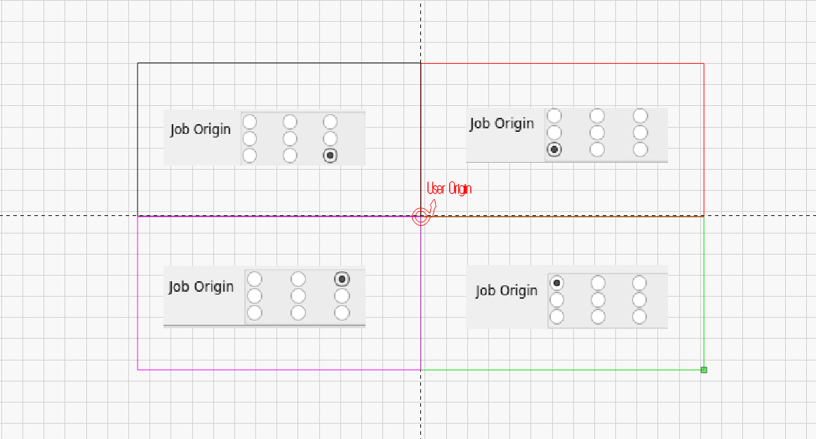
For the other two modes of start from, current position and user origin, you also have the job origin.
Both work the same way, current position is where the head is and user origin has be set to some value.
Job origin is required to place it on your laser … This is 4 rectangles and where job origin places them. In this case, user origin and current position are the same…
Appreciate the info BUT I’m still struggling with consistent use of the chuck rotary. I configured chuck in rotary setup and that’s OK, I use Current Position/Center Dot - place my laser on the spot on the tumbler that I want it to start from to engrave/etch my image [my rotary is placed so that it sits in the middle of the X and Y frame of my Ray5] - what is when I hit circular frame, I get this message pretty regularly “ALARM:2 G-code motion target exceeds machine travel. Machine position safely retained. Alarm may be unlocked. (Right-click the ‘Devices’ button to reset the connection) On or near line 4:”
I have to fiddle around with the rotary placement, to get it to work, this is pretty regular. I must not be using coordinates properly. Can’t figure out why I get this message because there is plenty of left and right X and Y movement available for the laser head to move. I have gone onto YouTube and researched other areas and I just can’t seem to figure this out. I have an order for several dozen tumblers and I’m having trouble here. Any thoughts would help or directing me in another direction to learn. Somewhat at a loss here.