Looking for a definitive list of parameters stored in a .clb file

Hi all,
I’m trying to generate a .clb file programmatically rather than enter every material through the UI. I have a spreadsheet of settings and want to emit valid XML directly. I know this topic has come up before (the CSV→CLB direction in the 2025 thread, the export-to-Excel thread, and the LBRN2 XML doc request), but I haven’t found a definitive parameter reference, so I’m asking here in the hope of producing one.

What I’ve found so far: The .clb format is simple, well-structured XML LightBurnLibraryMaterialEntry (with Thickness/Desc) → CutSetting (with a type attribute and a flat list of <Xxx Value="..."/> children). I’m aware there’s no official schema published; I’m hoping the community (or LB staff) can help crowd-source one.

main problem no 1:1 map between the UI and XML. Saving a library export does not faithfully reproduce every UI field. Concretely:

Plaintext

<?xml version="1.0" encoding="UTF-8"?> <LightBurnLibrary DisplayName="polar_cut_library"> <Material name="Granite Coaster Z9.0"> <Entry Thickness="-1.0000" Desc="Two Passes"> <CutSetting type="Scan"> <index Value="0"/> <name Value=""/> <LinkPath Value="Granite Coaster Z9.0/-1.0000/Two Passes"/> <minPower Value="20.5"/> <maxPower Value="20.5"/> <minPower2 Value="10"/> <maxPower2 Value="20"/> <speed Value="250"/> <PPI Value="0"/> <runBlower Value="0"/> <numPasses Value="2"/> <dotTime Value="1"/> <overscan Value="0"/> <priority Value="0"/> <tabCount Value="1"/> <tabCountMax Value="1"/> </CutSetting> </Entry> </Material> </LightBurnLibrary>

  • The runBlower element was absent from my export until I toggled Air Assist to off in the UI and re-exported. So elements appear/disappear based on UI state, which means “whatever the exporter happened to write” is not a reliable complete set.
  • The names don’t match the UI labels 1:1: runBlower <> “Air Assist”, PPI <> “PPI” (but behaves differently for Scan vs Cut), overscan, dotTime, tabCount/tabCountMax, priority, the minPower2/maxPower2 pair, etc. Several UI controls clearly map to non-obvious element names.

What I’m asking for ideally a table like this, filled in for every element a CutSetting can contain:

XML element UI label / meaning Type / units Default (when omitted) Applies to (Cut / Scan / both) Notes
minPower Min power (%) float 0–100 ? both?
maxPower Max power (%) float 0–100 ? both?
minPower2 / maxPower2 ? second power range? float ? ? when are these used?
speed Speed (mm/s) float ? both
PPI PPI int 0 ? 0 = off/default?
runBlower Air Assist on/off 0/1 ? both only emitted when toggled off why?
numPasses Pass count int 1 both
dotTime Dot time (ms)? int 1 Scan?
overscan Overscan (%) or distance float 0 Scan
priority ? int 0 ?
tabCount / tabCountMax Tabs? int 1 / 1 Cut
index ? internal int 0 both always 0?
name ? string “” both always empty in exports?
LinkPath material/thickness/desc path string auto both must match ancestors?
... (what else exists?)

Specific questions, in case a full table is too much to ask:

  1. Is there a complete list of every possible <Xxx Value="…"/> element under CutSetting for current LightBurn (as of mid-2026)? i.e. the superset, not just what a particular export happens to write.
  2. For each element: what is the default applied when the element is omitted? (The runBlower-only-when-toggled-off behavior tells me there’s an implicit default, but I don’t know which way.)
  3. Is there a canonical mapping between these internal names and the Cut Settings Editor UI controls? Especially: runBlower<>Air Assist, minPower2/maxPower2, dotTime, overscan, priority, tabCount/tabCountMax, PPI semantics for type="Scan" vs type="Cut".
  4. What are the valid values for CutSetting type="…"? I’ve seen Scan and Cut; are there others (e.g. for diode/galvo/MOPA-specific modes)?
  5. Does LinkPath have to exactly equal Material/@name/Entry/@Thickness/Entry/@Desc, and what happens on mismatch? Is it used as a key or just a display hint?
  6. For Thickness="-1.0000" is -1 the convention for “no thickness / variable thickness”? Any other sentinel values?

I want to author a library from a spreadsheet (lots of material/thickness/speed/power combos) without clicking each one in the UI. If I can get a reliable element→default→UI map, I’ll write a small generator (and am happy to share it). Even a partial authoritative answer “here are the elements, here are the defaults, here’s what runBlower/minPower2 actually mean” would save me (and others) a lot of trial-and-error and avoid shipping a library with incorrect defaults.

If LB staff can chime in with the actual internal struct layout that gets serialized, that would be ideal but community-sourced “I toggled X and element Y appeared with value Z” observations are also extremely welcome. I’ll try to post a consolidated table from the replies so it’s a reference going forward.

Thanks!

It’s not a small list.

There are some types used, like Cut Type, Image type, etc:

enum CutType
{
    CT_Cut,
    CT_ScanVector,
    CT_OffsetVector,
    CT_ScanThenCut, //deprecated. Still here for reading old files
    CT_ScanImage,
    CT_Tool,
};

enum ScanOpt {
	SO_Individual,
	SO_ByGroup,
	SO_MergeAll,
};

enum DitherMode {
	DM_Threshold,
	DM_Ordered,		// Ordered dither (Bayer)
	DM_Atkinson,	// Atkinson dither
	DM_Dithered,	// Floyd-Steinberg
	DM_Stucki,		// Stucki dither
	DM_Jarvis,		// Diffused JJN dither
	DM_Newsprint,	// Ordered dither (SuperCell)
	DM_Halftone,
	DM_Sketch,		// Useful for line drawings and sketches
	DM_Grayscale,
	DM_3DSlice,		// Galvo only, 3D multi-pass threshold
	DM_DotMode,
};

And there are tab parameters:

struct TAB_PARAMS {
	bool	tabsEnabled = false;
	bool 	manualTabs = true;		// true for manual placement
	float	tabSize = 0.5;
	bool	tabsUseSpacing = true;	// false means use count
	int 	tabCount = -1;		// either tabCount or tabSpacing used
	int		tabCountMax = -1;
	bool	limitMaxTabs = false;
	float	tabSpacing = 50;
	bool	skipInnerTabs = false;
	float	tabCutPower = 0;
};

Per sub-layer, there are these:

struct CUT_PARAMS {
	CutType type = CT_Cut;  // IE Line mode

    bool    suboutput = true;
	float	minPower = 20, maxPower = 20;		// in percent  (machine uses percent x 163.83)
	float	minPower2 = 20, maxPower2 = 20;	// in percent  (machine uses percent x 163.83)
	bool	enableLaser1  = true, enableLaser2 = false;
	bool	defaultPower1 = false, defaultPower2 = false, defaultSpeed = false;

	int		frequency = 20000;			// in hz
	bool	overrideFrequency = false;

	int		fiberPulseWidth = 100; // 2-500 ns

	float	speed = 100;				// in mm/sec   (machine uses micrometers/sec IE mm/sec x 1000)
	float   kerf = 0;				// Kerf offset in mm
	float	zOffset = 0;			// Initial cut-in offset for Z
	float	uOffset = 0;			// For machines that support a U axis

	int		numPasses = 1;
	float	zPerPass = 0;			// Move Z by this amount per pass

	float	startDelay = 0;			// aka Open delay   (OR, MinDotDelay in Image Dot Mode)
	float	endDelay = 0;			// aka Close delay  (OR, MaxDotDelay in Image Dot Mode)
	float	throughPower = 0;		// aka Through Power (%)
	float	throughPower2 = 0;		// aka Through Power (%)

	bool	EnableCutThroughStart  = false;	 // through mode for path start
	bool	EnableCutThroughEnd = false;	 // through mode for path end

	bool	perforate = false;
	float	perfLen = 0.1;			// length of the perforation cut (or dwell time in ms)
	float	perfSkip = 0.1;			// distance to skip between them

	bool	dotMode = false;
	float	dotTime = 0;
	float	dotSpacing = 0.1;

	int		PPI = 200;
	bool	enablePPI = false;

	bool	runBlower = true, autoBlower = false;
	bool	blowerSpeedOverride = false;
	float	blowerSpeedPercent = 100;

	float	overcut = false;			// distance in mm
	float	rampLength = 0;
	bool	rampOuter = false;			// Ramp the outer (enclosing) path too?

	bool	doLeadIn = false;
	bool	doLeadOut = false;
	float	leadLength = 0;
	float	leadAngle = 0;
	LEAD_STYLE	leadStyle = LS_Arc;

	// Scan only
	bool		biDirectional = true;
	bool		crossHatch = false;
	bool		floodFill = false;
	bool		autoRotate = false;		// Continuous rotation
	ScanOpt		scanOpt = SO_MergeAll;	// Individual, by-group, or all at once
	float		interval = 0.1;
	float       angle = 0;          // In degrees: 0 = horizontal, 90 = vertical
	float		anglePerPass = 0;

	float		dotWidth = 0;		// Stored as the full width of a dot produced by the laser, used when "beam "dot correction" is enabled
	bool		useDotCorrection = false;	// Enable / Disable line length adjustment
	bool		isCleanup = false;			// Is this a cleaning pass for 3D Slice?

	bool		overscan = true;
	float		overscanPercent = 2.5;
	float		dccValue = 100;

	// galvo specific settings
	float	QPulseWidth = 200;      // in ns
	int     LaserOn_TC = 100;       // in us
	int     LaserOff_TC = 100;      // in us
	int     End_TC = 100;           // in us
	int     Polygon_TC = 100;       // in us
	float   JumpSpeed = 4000;        // in mm/s
	int     MinJumpDelay = 10;     // in us
	int     MaxJumpDelay = 85;     // in us
	float   JumpDistLimit = 10;    // in mm
	float	wobbleStep = 0.05;
	float	wobbleSize= 0.1;
	bool	wobbleEnable = false;
	bool    OverrideGalvoTimings = false;
	bool	useAltSource = false;
	// end galvo settings

	bool tabsEnabled = false;

	QString subname = "";

	bool forceConstantPower = false;
};

And then per layer we have these:

    QString LinkPath;

	QString Name;

	int		priority = 0;
	int		globalRepeat = 1;

	bool	frame = true;
	bool	output = true;
	bool	hide = false;

	TAB_PARAMS tabs;

	// Scan image only - not in CUT_PARAMS because multi-image settings would break a lot of UI
    bool		negative = false;
	bool		passThrough = false;	// No resampling, DPI/Interval are tied to the image size
	DitherMode	mode;			// Threshold / Halftone / Random
	bool		enableCleanup = false;
	float		DPI;
	bool		linkDPItoInterval = true;
	float		cellsPerInch = 50;	// cell size for halftone
	float		halftoneAngle = 22.5;	// angle value for halftone

How does the Ruida know if it’s a cut or not? By the line/dither information?

I’d seen an RDWorks screenshot that appears to have a toggle for a cut/engrave.

:grinning_cat:

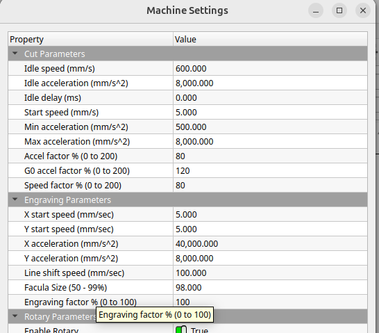
It doesn’t have any idea if it’s a cut - it’s “Line” or “Fill”. Line means “follow the line” and Fill means “scan between the lines”. The difference between cutting or not is a function of power and speed, and will depend on your machine.

The Ruida, at least mine, has a section for cutting and a section for engraving. How do these get selected? Or which is used where and how does it (the Ruida) know which mode it’s using?

The machine settings have both engrave and cut sections.

:grinning_cat:

This as a reference has worked an absolute treat! Thank you, Oz!

There is some obvious robot use, but I did not do so lazily. I tested all of the bits it threw in here, some multiple ways, and where I wasn’t able to I tried to note that. In my case there was not a use for each and every entry, so on the template you’ll only see notes on the ones I modified for my use.

CLB_TEMPLATE.clb (10.9 KB)

Building or Rebuilding a LightBurn Material Library by hand

How to use TEMPLATE.clb. Written while rebuilding a lost library for an OMTech
Polar 50W (Ruida CO2), but only the sections marked Machine are specific
to that.

Everything here was verified against, in descending order of authority:

  1. LightBurn’s CUT_PARAMS struct, published by Oz
  2. A .clb re-saved by LightBurn itself to verify what it reads and writes
  3. Two third-party libraries: Thunder Laser Mini 40W, and WAZER (744 total entries)
  4. The LightBurn 2.1 Material Library documentation

Where something is not verified, I tried to mention it. That said, do not trust anything in here
as I did involve an LLM for clarity and formatting. I used it, but that doesn’t mean you should.


Quick start

  1. Make a copy of TEMPLATE.clb and rename it.
  2. Change DisplayName on the root, this is the label in the Select Library dropdown.
  3. Keep one of the three example entries as a pattern, delete the rest.
  4. Load it: Window → Material Library → Manage Library → Load.

Everything is <tag Value="..."/>.


Hierarchy

LightBurnLibrary            DisplayName = dropdown label
  Material   @name          top folder          "Acrylic"
    Entry    @Thickness     sub-folder          "3.00mm"
             @NoThickTitle  sub-folder INSTEAD, when Thickness = -1.0000
             @Desc          the entry's label in the list
      CutSetting @type      "Cut" or "Scan"

Thickness and NoThickTitle are the same slot in the tree.
LightBurn greys out the Title box when a thickness is set, and greys out
Thickness when you toggle No Thickness on.

You want You write
Sub-folder reads 3.00mm Thickness="3.0000", no NoThickTitle
Sub-folder reads Cut Thickness="-1.0000" NoThickTitle="Cut"

Use a positive thickness when it makes sense, i.e. cuts.
Use -1.0000 plus a title for surface operations that don’t care how
thick the material is. It keeps engraves
from cluttering your thickness folders.

Group by family

Put the family in Material @name and the variant in Desc:

Plywood
  3.00mm  → Baltic Birch - 72% @ 18 mm/s
  6.00mm  → Baltic Birch - 88% @ 8 mm/s, x2
  Cut     → Plywood - 70% @ 15 mm/s        (thickness unknown)
  Engrave → Baltic Birch - 22% @ 350 mm/s, 254 DPI

One Material per "3mm Baltic Birch Plywood" gives you forty top-level
folders and no way to compare thicknesses side by side.

Putting the headline numbers in Desc makes contradictory
entries visible without opening anything, i.e., Slate - 60% sitting directly above
Slate Coaster - 28%.


Heats & Feeds

speed is always mm/sec in CUT_PARAMS, no matter what the UI shows.
The controller converts to µm/sec itself.
Paste a mm/min figure in and it runs 60× too fast. Convert first:

mm/sec = mm/min ÷ 60

minPower / maxPower are percent, 0–100. The controller applies its own
×163.83 scaling.

Raster spacing is interval, in millimetres, not DPI:

interval = 25.4 / DPI        300 DPI → 0.0847

interval only matters on type="Scan". Leave it at 0.1 on cuts.


Choosing power values

On Ruida, minPower applies during acceleration and deceleration:

  • Cuts - set minPower = maxPower, or corners may come out under-cooked.
  • Scans - minPower="0" is normal. Rastering runs at constant speed inside
    the overscan region, so the ramp value is of negligible value.

When saving

It rewrites the file sparsely. In a measured round trip it kept 9 fields and
dropped about 39. It keeps index, name, LinkPath, minPower, maxPower,
maxPower2, speed, priority, plus anything where the value differs from
CUT_PARAMS default.

Omitting a field is identical to writing its default. So you can write the
full 48-field block for a human-readable file, or only your non-defaults to
match what LightBurn produces. Both load the same. Entry 1 in the template is
the long form; entries 2 and 3 are the short form.

LightBurn also adds two items on save:

  • DisplayName on the root.
  • LinkPath per CutSetting, as Material/Thickness/Desc.

The template omits LinkPath on purpose. That format is confirmed only for
entries with a thickness; the no-thickness form is unverified, and entering a wrong
value might break Link. LightBurn regenerates it on save and it only
affects Link, not Assign, so nothing seems to break without it.


Sub-layers

LightBurn renders the sub-layer tab as 1 Cut it prefixes the index
itself. So never put an ordinal in subname, or you get 1 Pass 1.

Name by role, since position is already shown:

Situation subname values
Single sub-layer Cut or Engrave
Two-stage vector ScoreCut
Char cleanup CutCleanup
Engrave then cut out FillCut
Passes differ only by depth Cut Z-0Cut Z-2

The Output Sub-Layer toggle is suboutput in the struct, so you can ship a
preset with an optional pass disabled by default, a Score sub-layer, off
until you want it.

Unverified: I’m not sure how LightBurn serializes more than one sub-layer per entry.
Every entry in my sample set only had 1 CutSetting, and I couldn’t be bothered to check.
Sibling CutSetting elements under one Entry is the likely shape, but it’s still
a guess. Build a two-sub-layer entry in LightBurn, save, and read the file. Or maybe a
LB guru can help us.


What I didn’t find in the library

DitherMode, DPI, negative and passThrough are per-layer properties and
not CUT_PARAMS. A library entry structurally cannot store “use Stucki
dither.” I would note it in the Desc as a reminder to set it on the
layer.

Related: type="Scan" is CT_ScanVector Fill mode. For photographs you want
Image mode (CT_ScanImage). A Scan preset still gives you the right speed and
interval; you just have to set the dither yourself.


Machine-specific choices in the template

These are the settings specific to my OMTech Polar 50W. I can’t guarantee they’ll work
even for your OMTech Polar 50W, so there are no warranties, guarantees, and any use is
at your own risk.

Field Value Why
speed ceiling 500 mm/s Polar’s rated max speed
frequency 20000 Hz glass tubes don’t care
runBlower 1 The Polar ignores the off setting. Air Assist always runs.
enableLaser2 0 Single tube machine
overscan 0 See below

overscan is the one deliberate shift. CUT_PARAMS defaults it to
1; the template ships 0, following the Ruida-class reference library, the
DSP does its own acceleration ramp outside the image area. If raster edges come
out dark, set it to 1.


Sanity checks

  • every speed ≤ your machine’s max, and > 0
  • every power 0–100, with minPowermaxPower
  • every NoThickTitle paired with Thickness="-1.0000"
  • every Thickness formatted to 4 decimals
  • every Scan entry’s interval25.4 / intended DPI
  • (Thickness, Desc) unique within a Material duplicates collide

Validate before loading:

python3 -c "import xml.etree.ElementTree as ET; ET.parse('MyLibrary.clb'); print('ok')"

Generating these from a spreadsheet

If you’re transforming a CSV into entries, key your lookup tables on the full
identity
material, variant, thickness, and operation. A key of
(material, variant, operation) will match both the 3mm and 6mm rows of the
same material and mislabel one of them. That happened twice while
building this, in both directions, and neither showed in the output
without digging.

Assert that every lookup key matches one row. That’ll catch the whole class.

Here’s some more slop if anyone is still hungry. I was able to get chack jippity to generate the table I was originally after using Oz’s info my file spelunking and some ruida sources.

CutSetting element reference

How to read the columns

  • Type / units — the value is always a string in the Value attribute.
    This is how LightBurn interprets it. Booleans serialize as 0 / 1.
  • Default — the value LightBurn assumes when the element is omitted.
    Omitting an element and writing its default are identical (see “Sparse
    files” below). Booleans shown as their 0/1 serialization.
  • Applies to — whether the field does anything for a Cut layer, a Scan
    (fill) layer, or both. “Both (inert unless…)” means it’s written for both but
    only acts when some enable flag is on.
  • Confidencestruct = value confirmed against the CUT_PARAMS source;
    observed = additionally seen in a real file; inferred = reasoned from
    related fields, flagged so you can verify.

Enum string forms (scanOpt, leadStyle, and the layer-level dither mode)
are listed under the table.


Power, speed, passes

XML element UI label / meaning Type / units Default Applies to Notes
minPower Min Power % float, 0–100 percent 20 both Power during accel/decel on Ruida. Cuts: set = maxPower or corners under-burn. Scans: 0 is normal. Controller applies ×163.83 itself — do not pre-scale.
maxPower Max Power % float, 0–100 percent 20 both Primary cutting/engraving power.
minPower2 Min Power % (2nd source) float, 0–100 percent 20 both Inert unless enableLaser2=1.
maxPower2 Max Power % (2nd source) float, 0–100 percent 20 both Inert unless enableLaser2=1. Always written by LightBurn even so.
speed Speed float, mm/sec 100 both Always mm/sec in the file regardless of UI display units. Paste mm/min and it runs 60× fast. Controller stores µm/sec internally.
numPasses Number of Passes int, ≥1 1 both
zPerPass Z step per pass float, mm 0 both Lowers Z each pass; needs a Z axis.
forceConstantPower Constant Power Mode bool 0/1 0 both Disables Ruida’s power-follows-speed ramping. Not seen in sampled files; struct.

Laser source, frequency, PPI

XML element UI label / meaning Type / units Default Applies to Notes
enableLaser1 (Laser 1 enable) bool 0/1 1 both
enableLaser2 (Laser 2 enable) bool 0/1 0 both Dual-tube machines only.
defaultPower1 “Default” power toggle bool 0/1 0 both When 1, uses the machine/device default instead of the stored power. Keep 0 in a library or your saved power is ignored. struct.
defaultPower2 “Default” power toggle (2) bool 0/1 0 both As above, second source. struct.
defaultSpeed “Default” speed toggle bool 0/1 0 both When 1, uses device default speed over the stored value. struct.
frequency Frequency int, Hz 20000 both Machine: CO2 glass tubes ignore it; RF, fiber and galvo honor it.
overrideFrequency Enable Frequency override bool 0/1 0 both frequency only takes effect when this is 1.
fiberPulseWidth Pulse Width int, ns (2–500) 100 both Fiber only. Not in CO2 files; struct.
PPI PPI int 200 both Pulses-per-inch. Inert unless enablePPI=1.
enablePPI Enable PPI bool 0/1 0 both

Air assist / blower

XML element UI label / meaning Type / units Default Applies to Notes
runBlower Air Assist bool 0/1 1 both Machine: Polar has built-in air; leave 1 as the safe CO2 default.
autoBlower (auto blower control) bool 0/1 0 both Blower follows laser-on state.
blowerSpeedOverride Override blower speed bool 0/1 0 both
blowerSpeedPercent Blower speed % float, 0–100 100 both Inert unless blowerSpeedOverride=1.

Geometry / offsets

XML element UI label / meaning Type / units Default Applies to Notes
kerf Kerf offset float, mm 0 both Beam-width compensation.
zOffset Z Offset float, mm 0 both Focus offset; needs a Z axis.
uOffset (U axis offset) float, mm 0 both U-axis machines only. struct.
priority (layer order) int 0 both Cut order. LightBurn always writes it. Layer-level.
overcut Over cut float, mm 0 Cut Extends closed paths past the start point to seal them. Struct type is odd (declared float); treat as mm.
rampLength Ramp Length float, mm 0 Cut Power-ramp lead distance for cut-in.

Cut-through / delays

XML element UI label / meaning Type / units Default Applies to Notes
startDelay Open delay float, ms 0 both In image dot mode this is MinDotDelay instead. LightBurn writes it live.
endDelay Close delay float, ms 0 both MaxDotDelay in dot mode.
throughPower Through Power % float, 0–100 0 Cut Power for the cut-through dwell.
throughPower2 Through Power % (2) float, 0–100 0 Cut Second source.
enableCutThrough Cut Through bool 0/1 0 Cut Maps to EnableCutThroughStart. The struct also has an …End flag not seen as separate XML; inferred that the single tag drives start.

Perforation / dot mode

XML element UI label / meaning Type / units Default Applies to Notes
perforate Perforation Mode bool 0/1 0 Cut Dashed cutting.
perfLen Cut (perf length) float, mm 0.1 Cut Length of each cut segment (or dwell ms).
perfSkip Skip (perf gap) float, mm 0.1 Cut Gap between segments.
dotMode Dot Mode bool 0/1 0 both Fires at intervals instead of continuously.
dotTime Dot time float, ms 0 both Dwell per dot.
dotSpacing Dot spacing float, mm 0.1 both

Scan / fill only

XML element UI label / meaning Type / units Default Applies to Notes
interval Line Interval float, mm 0.1 Scan Raster line spacing. interval = 25.4 / DPI (300 DPI → 0.0847). Ignored on cuts.
bidir Bi-directional Scanning bool 0/1 1 Scan Maps to struct biDirectional. 0 = scan one direction only.
scanOpt Scan Mode enum (see below) mergeAll Scan Individual / by-group / all-at-once.
crossHatch Cross Hatch bool 0/1 0 Scan Second pass at 90°.
floodFill Flood Fill bool 0/1 0 Scan Fills by region rather than scan lines.
angle Scan Angle float, degrees 0 Scan 0 = horizontal, 90 = vertical.
anglePerPass Scan Angle Increment float, degrees 0 Scan Rotates the fill angle each pass. Not in sampled files; struct.
overscan Overscan bool 0/1 1 (struct) Scan See divergence note below. Extra travel past each line’s ends so accel doesn’t darken edges.
overscanPercent Overscan % float, 0–100 2.5 Scan Overscan distance as % of line length, when overscan=1.
dccValue (dot-correction value) float 100 Scan Line-length adjustment magnitude. struct.
cellsPerInch (halftone cell size) float 50 Scan Halftone only. Layer-level in struct; LightBurn stores it here.
halftoneAngle (halftone screen angle) float, degrees 22.5 Scan Halftone only. Layer-level.

Beam / dot correction (galvo & advanced)

XML element UI label / meaning Type / units Default Applies to Notes
useDotCorrection Beam dot correction bool 0/1 0 both Enables line-length adjustment. struct.
dotWidth Dot width float, mm 0 both Full width of the laser dot, used when correction is on. struct.

Identity / layer-level (written inside CutSetting, not CUT_PARAMS members)

XML element UI label / meaning Type / units Default Applies to Notes
index (internal) int 0 both LightBurn always writes it.
name Name string "" both Becomes the layer name on assign. Material hierarchy reads well: Acrylic 3.0mm Clear.
subname Sub-Layer Name string "" both Tab renders as 1 <subname> — LightBurn prefixes the index, so no ordinals (Pass 11 Pass 1). Name by role: Score / Cut / Cleanup.
doOutput Output bool 0/1 1 both Struct output. 0 = layer present but not run.
suboutput Output Sub-Layer bool 0/1 1 both Per-sub-layer output toggle. Ship an optional pass off by default. struct.
hide (hide layer) bool 0/1 0 both
LinkPath (internal link key) string regenerated both Material/Thickness/Desc. LightBurn rewrites on save; only affects Link, not Assign. Omit — the no-thickness form is unverified.

Tabs / bridges (TAB_PARAMS)

XML element UI label / meaning Type / units Default Applies to Notes
tabsEnabled Tabs / Bridges bool 0/1 0 Cut Whole tab block is inert unless 1.
tabCount Tabs Per Shape int -1 Cut -1 = unset; either count or spacing is used, not both.
tabCountMax Max Tabs int -1 Cut
tabSize Tab Size float, mm 0.5 Cut struct.
tabSpacing Spacing float, mm 50 Cut struct.
tabCutPower Tab Cut Power % float, 0–100 0 Cut Reduced power across the tab. struct.
skipInnerTabs Skip Inner Shapes bool 0/1 0 Cut struct.

Lead-in / lead-out

XML element UI label / meaning Type / units Default Applies to Notes
doLeadIn / leadIn Lead In bool 0/1 0 Cut WAZER writes leadIn; struct field is doLeadIn. observed tag name is leadIn.
doLeadOut Lead Out bool 0/1 0 Cut struct.
leadLength Lead length float, mm 0 Cut
leadAngle Lead angle float, degrees 0 Cut
leadStyle Lead style enum 0 (Arc) Cut See enums below.

Enum string forms

scanOpt (struct ScanOpt) — written as a string in the XML:

XML string Struct Meaning
individual SO_Individual Fill each shape before moving on
byGroup SO_ByGroup Fill grouped shapes together
mergeAll SO_MergeAll Fill everything on the layer as one region (default)

type on the CutSetting element itself (struct CutType):

Attribute value Struct Meaning
Cut CT_Cut Line / vector cut
Scan CT_ScanVector Fill (raster from vectors)
Offset CT_OffsetVector Offset fill
ScanImage CT_ScanImage Image mode — use for photos
Tool CT_Tool Tool layer (no laser output)

leadStyle (struct LEAD_STYLE) — seen as an int; 0 = Arc, 1 = Line
(inferred from enum ordering; verify if you use leads).


Layer-level properties a library preset CANNOT carry

These are per-layer, not CUT_PARAMS, so a .clb entry structurally
cannot store them. Set them on the layer and note the intent in Desc.

Property Why it matters
DitherMode Threshold / Ordered / Atkinson / Floyd-Steinberg / Stucki / Jarvis / Newsprint / Halftone / Sketch / Grayscale / DotMode. No library slot — “use Stucki” lives in the Desc.
DPI Image DPI is a layer/image property. The preset carries interval, which is the vector-fill equivalent.
negative Invert image.
passThrough Send image at native size, no resampling.
linkDPItoInterval Ties the two together.

I have a glass tube Ruida 6442g type.

You can set most any pwm period and the output pwm will use that period. You can test this by using a very low pwm period and you’ll see on a scope it does work, with a long pwm period, you can see the tubes power change doing a line.

Granted, it’s not worth much as the pwm is changed into an analog signal inside the lps. The lps input for current control is analog or digital.

Didn’t have time to get through it and I usually don’t reply to threads that have been solved. But I’d like to say thanks for the effort. :tada:

Although I wouldn’t have thought it, but it seems not all firmware handle things the same way.

Take care.

:grinning_cat: