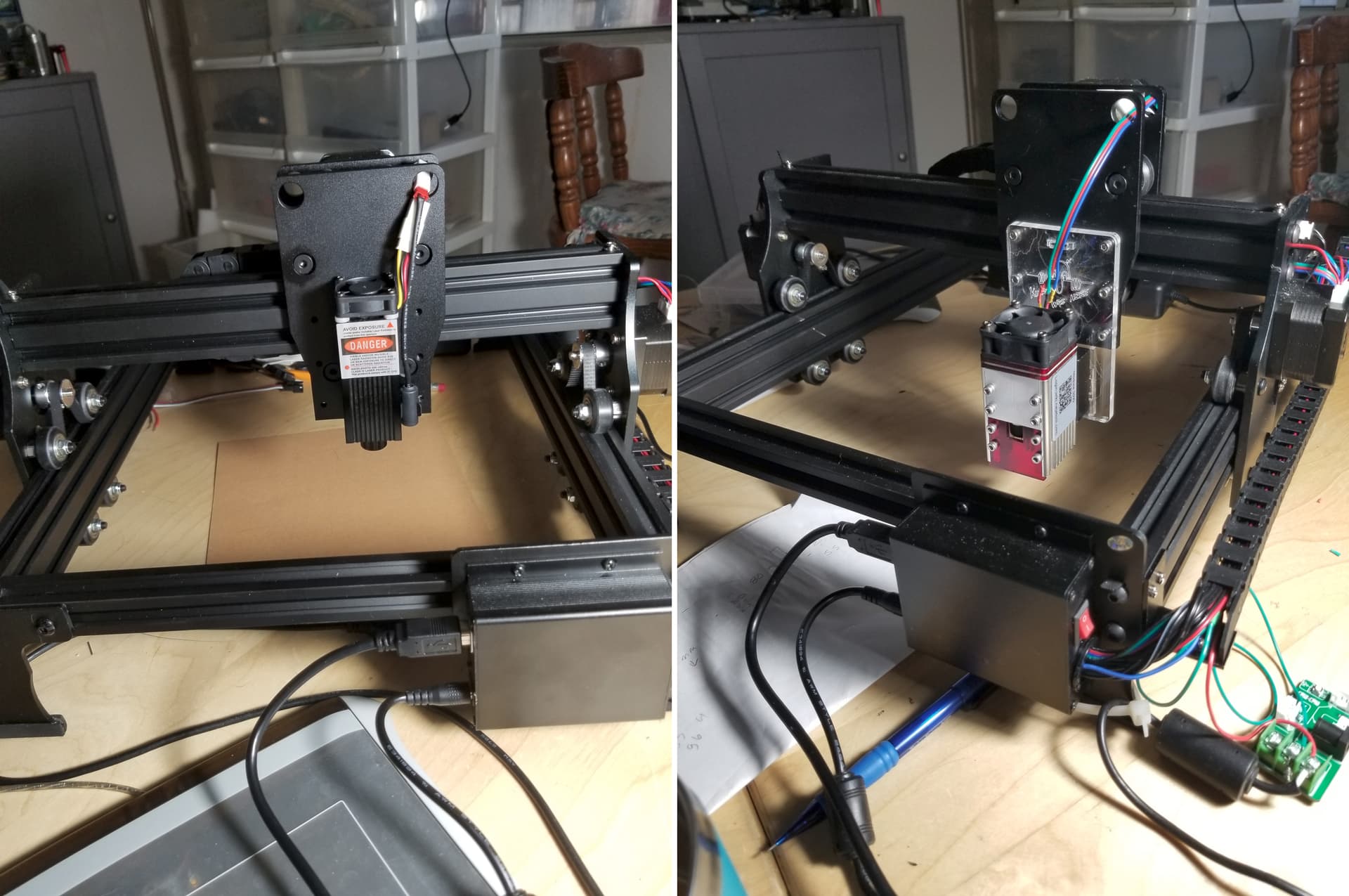
I have an Atomstack M100 mounted to a custom laser cutter I have built. The M100 uses TTL for control but my GRBL board only has PWM output. So I’m using a converter board I have tested it and at 100% power I get a smidge over 5v and at 50% i get a smidge over 2.5v (so the board seems to work)
I have a couple of issues. When i set values below 25% power The laser does to not fire. I adjusted a material test to take this into account however only the 100% row came out clean. It did not laser the text or the outline of the test and all the squares vertical lines were not marked at all. (will add photo when i’m home)
I’m using a board like this. but purchased form amazon.
The PWM output is frequency and signal level independent.
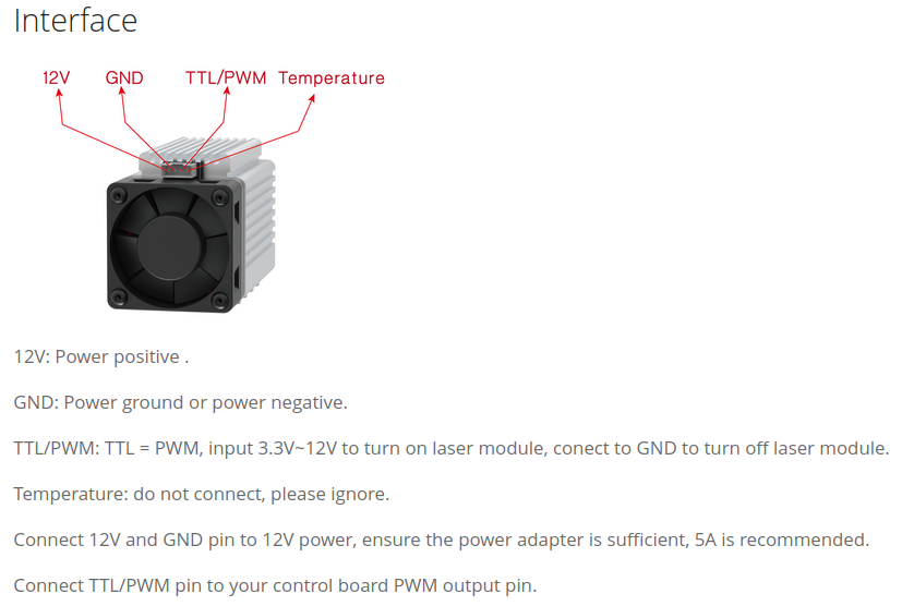
These outputs are ttl compatible pwm signals. You should be able to just wire the pwm output to the laser modules pwm input…
Make sense?
The converter you posted is not a pwm to ttl converter it’s a digital pwm signal to an analog output… the output of this board is incompatible with the required ttl signal by the laser module.
Thanks for the reply. Are you sure the Atomstack M100 will take a PWM singnal everything i can see says it only takes PWM and the laser module on the converter board is only marked TTL.
Ah no worries. That will be much simpler that way. I did scope the the output of the laser power board when I hit the test fire button it just output 5v where as my GRBL board output a distinct PWM signal on the scope. I assumed without trying that my board was not compadible with the my laser. I will take the board out and try it tonight.
There is a basic misunderstanding in terms, I think. TTL means transistor logic and only says that the signal follows the convention that a signal close to 0V is a logical 0 and a signal close to 5V is a logical 1. Nothing more. So most of the controllers and the components of your board use TTL for communication.
PWM is a special type of signal (in terms of the waveform).
In the end, for most diodes, it results in a PWM signal using TTL voltage levels. Which means, you have a PWM signal that uses 0V to 5V. As Jack said, just remove the converter board and directly connect those pins. On many mainboards you will find a mixture of TTL or PWM written on them because people (far east) don’t care or don’t understand.
Thanks. That really helped clear it up. I was assuming it was using 0-5v analog voltage to control the laser power. I have it all working now and getting some good results.