Hi all,
So i am using a falcon cr 10w laser module from creality to mount on my ender 3 S1. my machine homes in the front left. In lightburn i input my machine settings when I set it up, so using absolute cords and origin/home position to front left. In settings I also have it set to home first before print. Once I save a cut file to my sd card I turn on laser and it trys homing to bottom right of machine. im unsure why its doing that. any help would greatly be appreciated.
From another posting…
"The problem was the G54 which was wrong.
after some many tries the GRBL was messed up I set reset to default values and changed only the values needed . Yes I did use G10=0 any way using then G10 L2 P1 X-288 Y-178 Z0. "
Plug in YOUR X and Y values. Be sure to include the minus sign.
Enter $$ on the Console window to get the correct values in bold, using $130 and $131.
so lets assume i dont know much about editing gcode. and lemme make sure i didnt explain it wrong. besides steppers trying to go in opposte direction no matter what i tell settings my x0 and y0 is. x still trys going to the right and y forward. To hit my limit switches my bed needs to go to rear and x stepper needs to go to the left, and then of course inputing my x and y values where in lightburn?
Okay, this sounds like front-left homing. That should put you in the +X+Y quadrant, which Lightburn expects.
You are not editing Gcode, just entering it as a command. The little text box under the Console text window is where you enter stuff.
Enter the G10 string and see if it will Home properly.
First, does the machine move in the directions expected in the Move window?
I have to shut down soon and will be away from the computer for 14-15 hours. Someone may jump in to assist, but no guarantee. If a suggestion fails to work, be sure to include that in your reply.
so in move window. positive y direction brings me forward to the front of machine(bed moving to rear where limit switch is) and moving the x positive moves gantry to the left (torwards the limit switch) so it seems correct. so my bad but i didnt explain correctly when i spoke on editing gcode. litterly dont even know what to write in command box for the g10 string. just haven’t dived into gcode yet to get the basics.
This is confusing. There is no moving bed in a gantry machine.
The gantry moves front to back (Yaxis). The laser is mounted on the trolley that moves sideways (Xaxiz).
Like I said above, you enter the Gcode string in the Console window. The G10 command is the only one you will use for a long time, and it is only a one-time thing. We are not teaching you Gcode programming today.
Remember, you are our eyes and ears. We cannot see what you see, so you have to be very detailed and accurate for us to help you. All we know is what you tell us, and our suggestions for solving your problems depends on what you say.
Go slow and if you do not understand something we say, tell us. This is the Console window. The $NN reference is where you enter the G10 code.

There may be more questions, but this is enough for now.
ok sorry for being confusing but this is typical when someone that doesnt have all the techinal knowhow tries explaining something to a more experienced person. i am just explaining with words incorrecty i think. but as far as the bed i didn’t mean its a gantry system, in begining i mentioned this is a laser module mounted to my ender 3 s1. which the bed is the y axis. and the gantry the laser is mounted to is the x and z axis. or what alot people call it a bed slinger. again i wasnt trying to be confusing and i appreciate your time but as im seeing the laser community mostly understands the basic of gcode in all the threads so im deff at a loss there even understanding when people explain it to me. ill just do that first. thanks for your time.
We rarely try to be confusing, I just happens sometimes. ![]()
Yes, you did. My fault for not remembering you told me. I see you have a Laser head mounted on your 3D printer. I am thinking about doing that to my Geeetech machine!
Your 3D printer motion is similar to a Genmitsu table top CNC machine (got one of those too), so we will attack your problems with this view in mind.
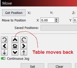
I will stay with you until I run out of experience. I assume (hope) you are trying the G10 part now. Next is to jog the machine to the place where it would hit the limit switches. Then click on the Get Position button in the Move window. We need the numbers that show up in the X and Y positions. Do not worry about the “Table” comment for now. I am reusing images I created for other postings.
ok so moved it to front left position. it says x 115 and y 50. but i remember reading somewhere on this site and i think i confirmed it. when i turn machine on wherever the laser module currently is it will start counting from there. i know obviously front left should be 0,0 and my build volume is 220x220 I input into the console window G10 L2 P1 X-0 Y-0 and hit enter. console says ok but laser head didnt move. but i did put it in the front left then did that console command. there is something else id like to mention in case its relavent. in my machine settings i have 220x220 for size. in console window i type $$ and it gives me a list and if i read right $130 and $131 should say my build size yes? cause they say $130=400.00 and $131=415.000 and if i do need to edit those values i really am not sure hw to do that. Also i manually placed laser head earlier and did some test prints but it comes out upside down vrs orientation on my screen in lightburn. not sure what that means but just remembered it if that has anything to do with the not homing issue.
I cannot do it now, but you gave us a lot of information to work with. You did good on the $$ thing. To change the $130 & #131 values, enter in the console window $130=200, and then $131=200.
I am thinking these have to be adjusted to compensate for the laser hanging out. But that is later.
To enable Homing, enter $22=1. If it tries to home in the wrong direction, set $22 back to zero.
so i changed the values and retyped $$ to make sure they saved and they are correct now. $22 was set to 1, so i changed it to 0 and just gave me an error saying homing isnt enabled in grbl settings so i set it back to 1. with that said i did try to home it after i put it back and of course it tried going to opposite side. im gonna try copy paste my grbl settings here. $0=10
$1=250
$2=0
$3=4
$4=0
$5=0
$6=0
$10=1
$11=0.010
$12=0.002
$13=0
$20=0
$21=0
$22=1
$23=3
$24=1500.000
$25=4500.000
$26=20
$27=3.000
$30=1000.000
$31=0.000
$32=1
$100=80.000
$101=80.000
$110=10000.000
$111=10000.000
$120=500.000
$121=500.000
$130=220.000
$131=220.000
This is good, we are making progress.
Set $22=0 We will change it later)
Before changing any GRBL parameters related to Homing, we have to make sure motion control is correct, or not.
Jog the machine to near the middle of the table.
Does left and right (Xaxis) move correctly according to the buttons?
Does the UP arrow (Zaxis) move the table away from you?
Does the Zaxis travel match the dotted arrows on the Move window keypad?
Jog the machine to where the Home switches are located, as close as you can get.
Turn it off, then back on.
In the Move window, click the Get Position button.
What does it show for X:?
What does it show for Y:?
The answers to all these questions will determine our next move.
1 Like
ok so at my work i use a miling machine (non cnc) ans when i first started using that machine for the first time alot years ago it took me a bit to remember when u wanted to for example drill a hole in your piece on the left side you had to move your x axis bed to the right cause the head is stationary. im assumeing this is same idea. reason i said that is the arrow control pad in move up arrow brings bed to the rear but brings the head up. so it seems like that. but when i hit left arrow (- direction) on move window it moves laser module to the right (if your standing in front looking at the printer) i guess my point is what relationship is lightburn putting those arrows to on machine. cause if its meant to be looking at machine from rear (or top view looking down) the arrows move correct. top arrow moves laser forward, left arrow moves it to the left, right to right and back to the rear.( the top and right arrow in lightburn both positive arrows move the laser to front right if standing from rear or that would be front left standing in front of machine ) i hope that wasnt confusing but i deff think i should understand how the arrows in lightburn consider u looking at machine.
The z axis is not used on my model. this one i adjust focus manually then engrave/cut.
I moved machine to where the limit switches are, basiclly touched them, turned machine off, turned back on hit that get posistion button and it gave me a x-0 y-0 which is correct.
$22 is set to 0
I wanted to make this a separate one. So with the question regarding the arrows relative to machine. If its meant to be looked at from the front of my machine then the y axis is backwards, when I hit down arrow the laser moves to the rear of bed, and to the front of bed when I hit up/top arrow. (if the arrows are really telling you its where the laser module is moving) but when I hit left arrow on my screen the laser (standing in front of the machine) moves to the right side. just wanted to recap on that part by itself incase my first message was to much back and forth with that part.
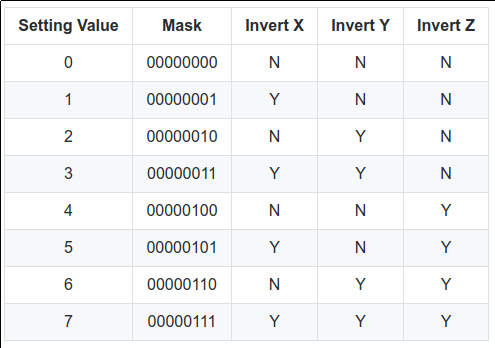
On my machine X- (using the jog controls) moves the head to the left (when facing the front of the machine) and X+ moves it to the right. Y- moves the head forward (i.e. the bed moves to the back, towards the limit switch) and Y+ moves the head to the back (the bed moves towards you). It took me awhile to be able to keep the jog direction straight in my head when going back and forth between CNC/3D machines and a standard laser. What worked for me was imaging that it’s the head moving, and the bed is stationary, then it makes sense. BTW, the $3 setting in GRBL lets you change the direction of the steppers if they don’t move in the direction you are expecting. Hope this helps.
1 Like
ok great! so mines doing exact opposite as yours. in my grbl settings my $3 is set to 4. what number is reverse that?
$0=10
$1=250
$2=0
$3=4
$4=0
$5=0
$6=0
$10=1
$11=0.010
$12=0.002
$13=0
$20=0
$21=0
$22=0
$23=3
$24=1500.000
$25=4500.000
$26=20
$27=3.000
$30=1000.000
$31=0.000
$32=1
$100=80.000
$101=80.000
$110=10000.000
$111=10000.000
$120=500.000
$121=500.000
$130=220.000
$131=220.000
ok
ok so i actually found a video on this!! i changed it to $3=7 cause both were backwards and my machine homed!!! with the help from both you im very happy thank you Paul and Mike.I had to enable auto homing again. check it 3 times each time it worked flawless. Now that it homed. i then shut machine off turned back on and my x-3 , y-3 . so its offset in by 3mm each way. so i need to do an offset? cause if i happen to cut something out with a border of 220 in either direction would that make it actually 3 shy of 220? or is that 3 on screen just if i make a 220 frame lightburn will say im gonna go out of bounds cause 220+3 is obviously over. but in reality the actual posistion is correct on machine just says 3 in lightburn
I was going to post this chart, but it sounds like you’ve got a handle on it.
The only thing I can think of for the offset is that, at least on my Ender 3, it homes just off the bed so that there is less of a chance of the nozzle crashing into the bed. $27 is set to 3 (i.e. 3mm pull-off distance) so I’m not sure why it’s saying -3. In the grand scheme of things, is 3mm going to be an issue? On my OLM2 Pro there is a 3mm pull off but there is room on the frame for it to still allow for the full 400mm. BTW, I have the bed size on my Ender 3 set to 235mm and haven’t had any problems. For the time being, I would leave $27=3 and see if you still get the full 220mm.
[quote=“JC2002, post:17, topic:123665”]
happen to cut something out with a border of 220
[
Trying to squeeze water out of a rock?
Set both $130 and $131 to =216. Your machine has lead screws, so hitting the frame limit is a very bad idea.
220mm = 8.66"
216mm = 8.504"
I doubt you are going to need that extra 4mm (or 0.156") for a project. If you do, you either need a bigger machine or use the Lightburn feature called Cut and Print. You are frame-limited by the 8.5" width, but (with supports, you could possibly burn an image the length of a 12’ board. That would be impressive!
Congrats on getting the parameters worked out! Success feels good, am I right? Now go have fun.
And expect to hear from me on putting a laser on a 3D printer. ![]()
1 Like
9 posts were split to a new topic: Creality Falcon Laser not homing