Marks/Bumps from Laser Refracting off Honeycomb Laser Bed (is that a thing?)

I measured the ‘hole’ left by the Honeycomb and had the steel place cut it to size. Removed the aluminum supports for the honeycomb and put the metal in the hole.

Good luck…

:smile_cat:

Compared to the other machines I have (had), it is a best :wink:

I use all 3 options I have, this perforated steel plate, my honeycob and the knife bed.
“My” steel plate has the advantage that it is easy to clean but still has the possibility of air being sucked from below, not so much but enough.

Oh dear… So, I must’ve grabbed the wrong kind of sheet metal. The reflection is melting underside of the material like crazy lol pretty gross looking and seeing lots of fire o.O Currently using the honeycomb again to cut out some standoffs I drew up that should give me about 13mm lift. Will try cuts from there and after that I’ll give it a try without the honeycomb and just the aluminum supports underneath.

Seem to be back at square one with everything. I’m also struggling again with my edges. Overall, they seem polished but lots of striation and of course those deeper cut spots from the reflection… My last run was 3mm @ 35% with the material resting directly on the honeycomb. Going to play with speed, power, focal distance, and distance of material from the bed throughout the evening. Doing these things with both extruded and cast acrylic in hopes that I can finD the sweet spots for both varieties of acrylic.

Side note, I’ve eliminated just about all vibration from my machine by suspending the air compressor up in the air with some heavy duty bungee cables. The compressor isn’t making any contact with the machine aside from the bungee cables. The bed has literally zero vibration after doing this hack. I hoped that it would help with striation and I did notice improvement but I must’ve screwed my settings up again as now the edges are back to bumpy.

I seem to be using the same focal distance and same settings as I did with previous decent looking cuts but am again off track. Is this the common course of events for newbies? Kinda feel like a dumbo atm.

I probably have not been clear enough, but spacers need to be used to prevent reflection and heat marks. This applies to all materials. In the case of non-perforated steel plate, this is even more true because the gases cannot escape from under the material. With wood and acrylic, I can regularly see and hear small gas explosions if, for example, I have not turned up the exhaust enough or there is not enough inflow of new air into the laser machine. It is related to gas-air mixing ratio, if the “right” mixing ratio is achieved, then the (small) explosions occur. (Mixing ratio for the ignition of gas / air is in the range of approx. 5-13%)
Most clearly I can observe this using my honeycomb bed.
So, plenty of exhaust and if possible plenty of fresh air, helps significantly to avoid smoke marks caused by small gas explosions.

I have to admit that I experiment a lot when I do not have more important things to produce because I like it. With lots of acrylic, up to 20mm which I buy relatively cheaply from a factory nearby as clipping scraps, I have plenty of options visually to see the difference of the different parameters.
When I have an order of acrylic items, I usually do a little test every time to confirm my existing values, often they do not fit 100% to just the acrylic tray I work with today, so adjustments are often necessary. My laser tube also varies a bit, all depending on the temperature and the time it has been running.
But up to 8mm I rarely experience problems.
My suggestion for a good result in acrylic is, perfect focus (on the surface of the material, even with thicker materials), not too much air in the cut, better use air under the material, if possible, to get rid of the gases and all the exhaust you have available.
Be aware that speed is more important for thick materials than the power setting. It takes some time for the gasification to come out of the cut. It can be seen very well when you make a pulse with 50% power and one or more seconds. Penetration continues for 7-9 seconds (at 60Watt). With 20mm / s you do not manage to utilize a fraction of the supplied energy. With 2mm / s on the other hand, you heat the material much more than necessary and it becomes unstable in its dimensions.
One must be patient and want to find the right parameters for the most optimal result. It takes time but the result makes the difference.

The picture shows an example of deformation.
(15mm, not finished)

Your Keyboard looks very nice and futuristic.

Even if these are large pieces you are working with, it might be worth a try to protect the items with tape.
A little later tonight I will do some tests with settings for 3mm acrylic, the test pieces I have had are made with my K40 and given away with the machine. I have tests with 4mm but the difference can be quite large to 3mm, so I make some new ones. (I will report back with the result if you are interested)
Setting the focus height that you use is certainly quite fine. I always use a generally simple ramp test, where I try with the largest possible angle, so it’s easier to see where the focus center is. But sometimes I also use the same setup to cut out small circles, typically they fall out where the focus is best. (I draw a whole row or two with 5-8mm circles and lay them on the lines I just made in the first ramp test and cut with the just found focus distance, the circles)

What do you do with the sharp edges that often occur when cutting acrylic? Do you use a knife or something else to scrape the items?

Sometimes I use a gas burner to re-polish the edges, it requires a little feeling but can give good results.

Thanks a bunch, the keyboard niche is a wacky one.

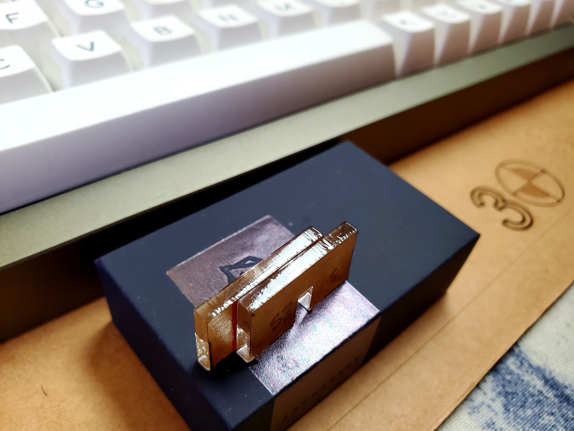
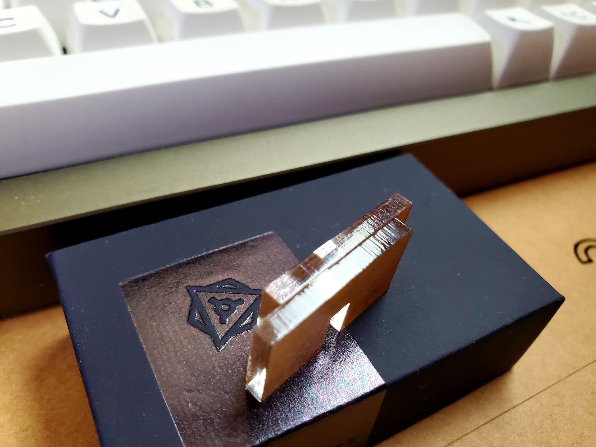
For sure, I’d love to see some of the tests you run. I found some settings that seem to give much better results. For 3mm Cast acrylic I went with 3mm/25% and then another at 5mm/35%. Results seem comparable but definitely a little more polish with 3mm/25%.

You brought up airflow and ambient temperature so I also set my inline fan to about half the speed it was running before. The machine is in the garage and it’s pretty cold so I’m thinking that had a lot to do with my 3mm acrylic cuts cooling down before the gases/heat trailing the laser had a chance to polish the edges.

For the time being I think these results are acceptable. Will cut some actual parts and see where I am from there with fitment. I haven’t really had issues with sharp edges from acrylic cuts. That said, I’ve only had my laser for a few weeks and haven’t done much in the way of actual production. The laser service I outsourced my parts from didn’t seem to have issues either. My parts typically were delivered still in their cut sheets of acrylic with an extra layer of masking on the back to sort of hold everything in.

I hadn’t thought about heat polishing with a burner. Something to try for sure. I often use Delrin for certain parts of my boards and I’d love to be able to polish all of those scratches out. POMs polished surface scratches like crazy so often times I sand it down to get a matte finish instead.

Here’s where I am so far: First image is 3mm/25% and Second image is 5mm/35% both using air assist with my inline fan at half the speed I was using before. Used these same parameters on some extruded acrylic as well and seemed to have more striation than we see with these cast samples.


I have also just finished my 3 mm acrylic test, here is the result.

The parameters I used are 15mm / s at 40% power = 10mA.
I have emphasized that the items should fall out completely by themselves and the cut surface should be the best possible. I’ve also run it with half the values, it’s going to be nice too. (8mm / s 25%) But there is no specific difference and I prefer to add as little heat as possible to the items. My favorite is the faster setting, this time
There is a pretty delicate drawing of step lines when I use a magnifying glass, but it is there at all speeds. When you do not know it, you will not be able to see it.

2 Likes

Wow, those look so clean! Really, thank you so much for the time you’ve put into helping me sort all of this out. I appreciate your support!

I’ll give that faster speed a try right now. I was just about to make some production cuts but ran into an issue with my scaling. Just when I thought we were back on track lol Turned out I needed to set my kerf outward which doesn’t make much sense as the standoff holes were coming out way bigger than intended in the first place. Anyhow, looks like we’re good to go in that arena.

Those cuts are primo for sure. In the first photo, was that at the higher 15mm / s at 40% power = 10mA speed? That edge is exactly what I’m looking for.

1 Like

Very nice work…

If you look back at the photo of the metal bed, you can see the vertical magnets I use to lift it off the plate.

I use these from amazon. Stack them so they are 4mm thick and stand them on their side for 5mm height above the table.

:smile_cat:

1 Like

It’s all right and you are welcome, I enjoy working and experimenting with my laser a lot, so it fits well together :wink:
Yes, the small elongated square and the rest of what is shown are made with the relatively fast speeds. It can also be made faster, but I feel best with these settings for 3mm acrylic.
Kerf, even though it should be easy, I also sometimes scrap parts because I think “reverse” once in a while. As recently as today, I had to do some intarsia work and also chose + instead of -, but that was only a small topic for my own pleasure :wink:

It is 3mm BB plywood and the LB monster :wink: is made of mahoni veneer.
Kerf is only assigned to the dark part, - 0.1mm

That’s genius, I’ll give the steel sheet another try with some magnets then. Thanks for the heads up!

I whipped up some acrylic standoffs and now have my material roughly 13mm above the bed. Better results but it would seem I need to go higher, still getting some reflection over a few different areas of the bed. I’ve leveled the the cutting area meticulously at this point and my standoffs hold the material level. I’ll assume some parts of mesh are just more reflective than others.

I can see the appeal of having options for honeycomb, aluminum slats, and steel sheet as a contributor previously mentioned. I need parts of all sizes cut so it’ll be great have each bed style dialed in.

I’m 5mm off the bed and I don’t have these issues…

If it’s going through, it is not very focused coming out. It travels another 13mm to the bed, becoming more spread out, then bounces off the whatever, travels another 13mm back up, more power loss… and burns the material…?

Maybe a ‘wee’ bit too much power…?

You need to slow down and think about what’s going on here…

Place the magnets so they are not struck by the beam… The bigger magnets are used to make a crude side/top stop ‘frame’ for the material.

If the reflection is doing damage, a part, not falling perfectly will be toast if it’s hit. One of the reasons that I keep it close to the bed. I usually get a pretty good ‘stream’ of debris gas out the back.

What doesn’t go out the ventilation, pretty much sticks to the steel plate.

Good luck

:smile_cat:

Okay, interesting. Overpowering could be the issue. Maybe I interpreted it incorrectly but from what I gathered through Russ’s tutorials was to bring slower speed and more power to the cut. That said, he used mostly 5mm acrylic. He also mentioned 3mm being much more difficult to get polished due to the lower heat/gas reaction polishing effect that takes place with thinner acrylic.

Regarding reflection - Maybe I grabbed the wrong sheet? What I got was a flattened sheet of cold rolled steel. Don’t recall the gauge atm. The sheet is definitely shiny which made me question its ability do what I needed it to do. You mentioned the steel being dirty, dark, with smoke sticking to it so as to not reflect back up. Is that similar to a cast iron pan? I mean, does the sheen in the metal need to gain a sort of seasoned coating from smoke before it stops reflecting? Trying to think of ways I’d be a le to dullen the sheen… Sorry for the rapid fire of questions, genuinely confused with the steel sheet reflection topic.

In terms of power level - I haven’t really tested above 40% So far my best results came from 3mm per sec @ 30% power (10ma from what I noticed) with a distance of 13m between bed and material + focal length of about 13mm. Would going lower be better? The lowest setting I’ve tested was 3mm @ 20% but it wasn’t quite enough to cut through. Could this possibly be a matter of some sort of hardware issue?

Thank you kindly for your time and consideration!

That looks pretty awesome :ok_hand: Love the idea of inlay.

Do you design solely in lightburn?

I think you can see how dark it is in the picture. I went to the local steel company with my measurements and asked them for ‘rolled steel’. It has always been relatively dark.

Remember, even the beam gets larger in diameter as the distance increases. This is exacerbated by the lens itself. Once it passes the focal point it will start widening. As it widens the power density spreads across the larger beam. If it reflects, a very small area will probably reflect and it has no ‘flat’ or focusing ability, so the reflected beam is scattered, weakened even more. This happens relatively quickly. If it didn’t you wouldn’t have to be so precise in focusing. The real power of the laser is the lens focusing the beam to the smallest spot.

I use high power, like in the 70% or greater and run as fast as I can, especially with thin material. Don’t remember off hand, but seems like the cutting speeds are around 7mm/s for 4mm and 3mm/s for 6mm @ 70% or about 16mA.

Just try to pick up as much as you can. You will develop ‘what works for you’, in time.

Take care, good luck

:smile_cat:

1 Like

Everything is made in LightBurn and the dragon itself is of course our everyone’s little pet from LightBurn :wink:
Sometimes when I want to find the limits of the materials, the machine and my own ability, I make these marqueterie / intarsia. Here at last I make them as about 40mm coins, the youngest kids of the whole family love them.
In fact, it is also a nice kerf test, everything is just pressed together no glue. (Saturn is not inlay)

It is a thing. I actually cut 20mmX20mm for squares of 1/8" or 3mm birch hobby ply and elevated my work piece off the honeycomb, though the rolled steel suggestion by Jack Wilborn is a much better solution.

I just use golf spikes, the threads fall perfectly into my honeycomb holes.

image

2 Likes

I don’t know if this is helpful at all, but I found that the powder-coated surface of the steel tray under my honeycomb was getting burned off by my laser (through the honeycomb), so I had the “bright” idea of adding a layer of aluminium foil over it, to prevent the beam from ablating the coating. I figured it would be fine with the matte side up. It was not. It bounced the beam back up to the underside of my piece and I got a bunch of wiggly lines and a scorchy gross mess all over it.

So I took the foil off again… and I just kinda deal with it… But maybe you could paint your steel sheet with something benign, to reduce the reflection?

If this worked, you could engrave aluminum… :wink:


For co2 machines, people use something that absorbs the emf, such as acrylic. Same idea for any laser…

The problem with any support that doesn’t absorb the emf, is that some of the energy will transfer to the material at the area of contact…

It’s tough to change that with a honeycomb bed or just v-shaped supports… I swapped mine out for rolled steel sheet… It still requires supports but makes for good air flow control…

:smile_cat: