I just wanted to share a little bit of design insight on developing material test cards, specifically the portion that deals with cut speeds.
What I have seen everyone doing is to make a bunch of small boxes in a row, about 20 to 25mm square, that they assign different cut speeds to, similar to this:

The problem with this method is that the laser rarely can get up to that speed in such a short distance, so you are never really cutting at this speed. That is why many times you will have sections of your work that do not cut through usually on long lines or long circles and arcs, because at that position of the work, the laser has had time to accelerate to the true speed you have set.
A better way to figure out the maximum cutting speed on a test card is to use concentric circles that you set to different speeds like this:
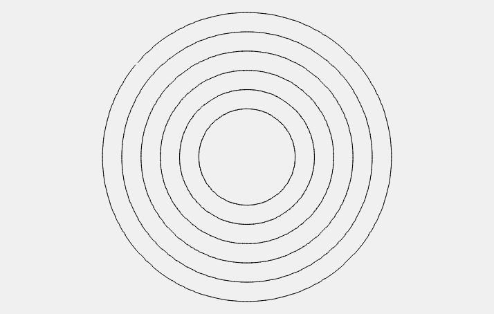
The laser will have time to accelerate to the actual speed you have set as there are no corners to slow you down and then have to accelerate again.
Hope this makes sense to you, and if you have any questions, feel free to ask