I am running a ComMarker Omni 1 (5 Watt) model and am doing some color marking tests on Stainless Steel surfaces (Polished).
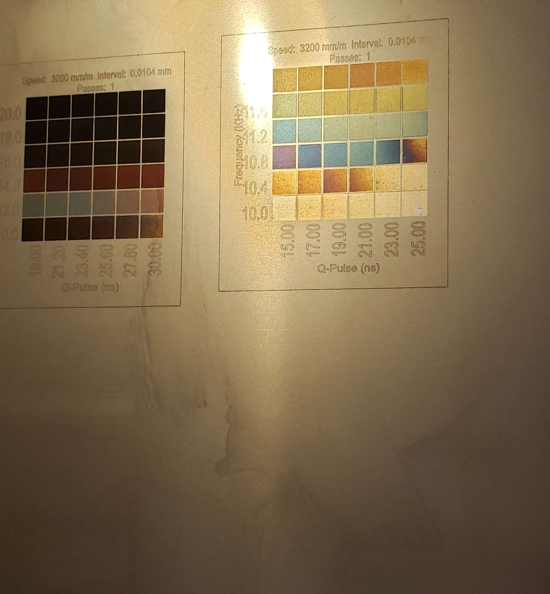
I am using the Material Test Tool in order to get a nice grid. By varying frequency and Q-Pulse i got this wonderful Palette of colors at 3200 mm/min (53mm/s), 0.0104 mm line width (2440dpi) and 1 pass.
You can see the purple-blue bands that i want i want to replicate. These settings keep the surface very shallow and smooth to the touch.
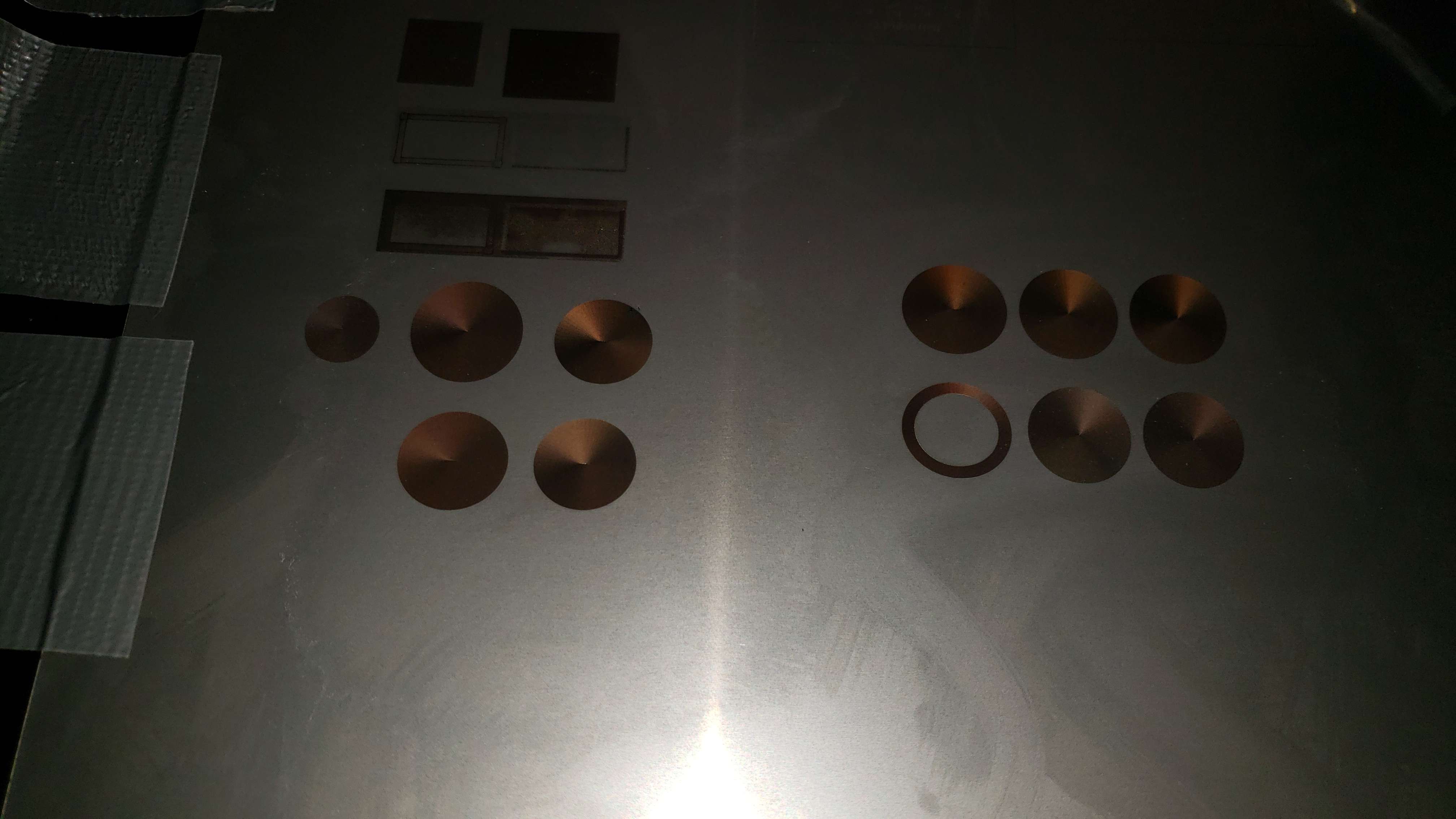
Unfortunately i cannot replicate these colors separately. If i just draw a square and use Fill with the Exact same settings as Material Test, then i only get red-brown shades. (Not best pic but the colors are almost all the same with darker lighter variations of red brown)
For example that Blue hue was 11KHz @ 17ns , 3200mm/min, 0.0104mm, 1 pass in the Material Test
But for the actual Test with the exact same settings it remains dark brown. And the other dark brown circles are actually supposed to be the other colors, but they are all dark brown.
Another thing i noticed is that during the materials test, when i was testing for high Qpulse (100-200ns), it was as if the laser magically adjusted the %power settings (despite that being commercialized impossible for a omni 1 UV laser) because the reflections and sparking on the metal surface were visibly lower, if almost non-existent completely.
My goal is to ideally achieve Blue, Pink/Lilac and as near to Red as possible while keeping the Speed and interval constant at 1 pass
I do not have a fiber machine, but I can do the same with a diode laser. You have two tests in the first image. In the second image, you are expecting the same results as you got in Image 1 right side. Yet your burn pattern is entirely different if I am seeing it right. It appears the circles were done with Offset Fill, but the squares were Fill (a raster scan). The heating of the stainless will not be the same.
Speaking of heating, There is a very fine line between the anneal colors with stainless. You are coloring it by basically heat treating the metal. How much you put in an area in a given time impacts how hot you get the stainless in that area. Not only do power and pulse rate make a difference, but also how much area your trying to heat and the path used to heat it. Stainless is a poor conductor of heat, but it does conduct. Even the ambient temperature will affect your results.
You do know you can create some colors, so the trick is finding the right settings for the particular pattern you are trying to create.
.
I actually fixed it. You indeed cannot really touch power settings but the problem was with speed.
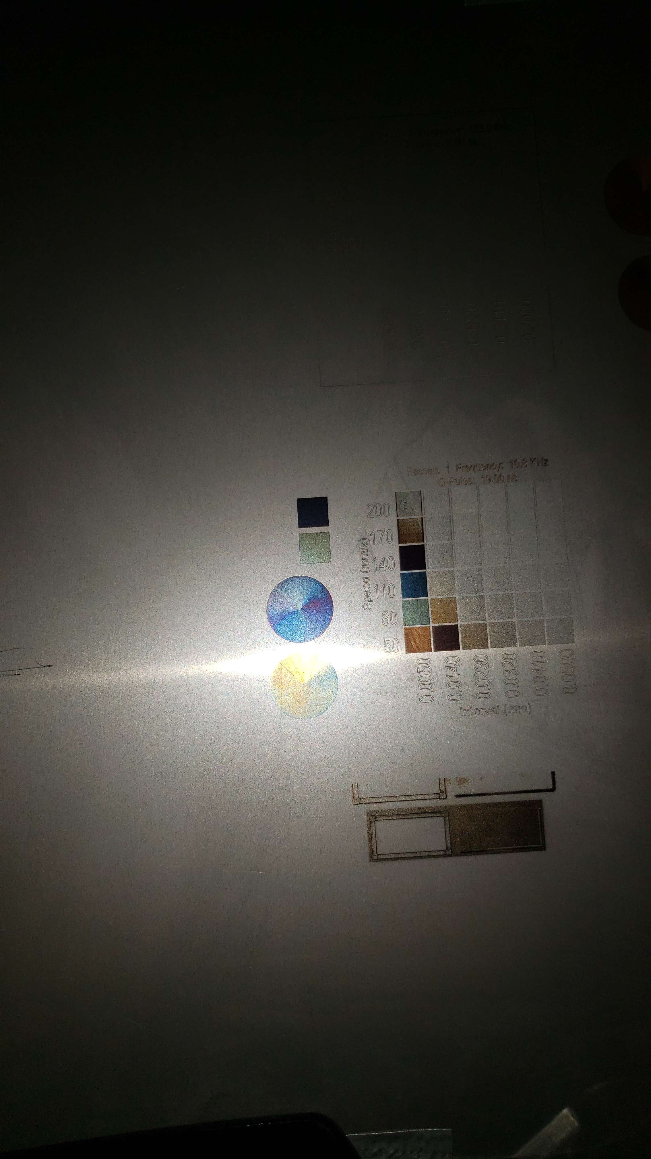
For some reason the Materials Test was taking my speed incorrectly so i changed it to the device settings in mm/s as default and it was going smoothly. I managed to get colors for both a straight raster and offset fill. Very accurate to each other. Both Blue and Lilac
Currently having struggles with actual images. Tried a black to white gradient and it simply does not do it like the actual Fill. Even in very dark regions. Using Jarvis dither for that
I’m convinced you have no idea what you’re achieving. Consistent results are rarely achieved in stainless steel. There are so many variables that the results, as a rule, do not coincide.
It all has to do with the temperature that stainless steel reaches, as @MickeyH mentioned.
If you search the forum you will find some discussions on the subject, and it is through these discussions that I have this opinion.
I’m amazed at the color variations you’ve achieved. Congratulations!
ntrolled to achieve the colors almost exactly the same.
For reference above those 2 circles are 110 and 80 mm/s at 0.005 mm line width. The 80 mm/s variant (light blue) started glaring a bit brown on the left side of the circle.
Atm am trying to keep the place very dry at 10 degrees celcius. The 0.4mm polished steel sheet has been tensioned on the engrave board as to have very minimal surface bumps. Also well cleaned with IPA at regular intervals.
I found that when engraving with some of these settings red oxide powder forms at the edges and can remain deposited on second passes. Becomes impossible to get off. Which is why i am trying to achieve these in 1 pass/constant speed.
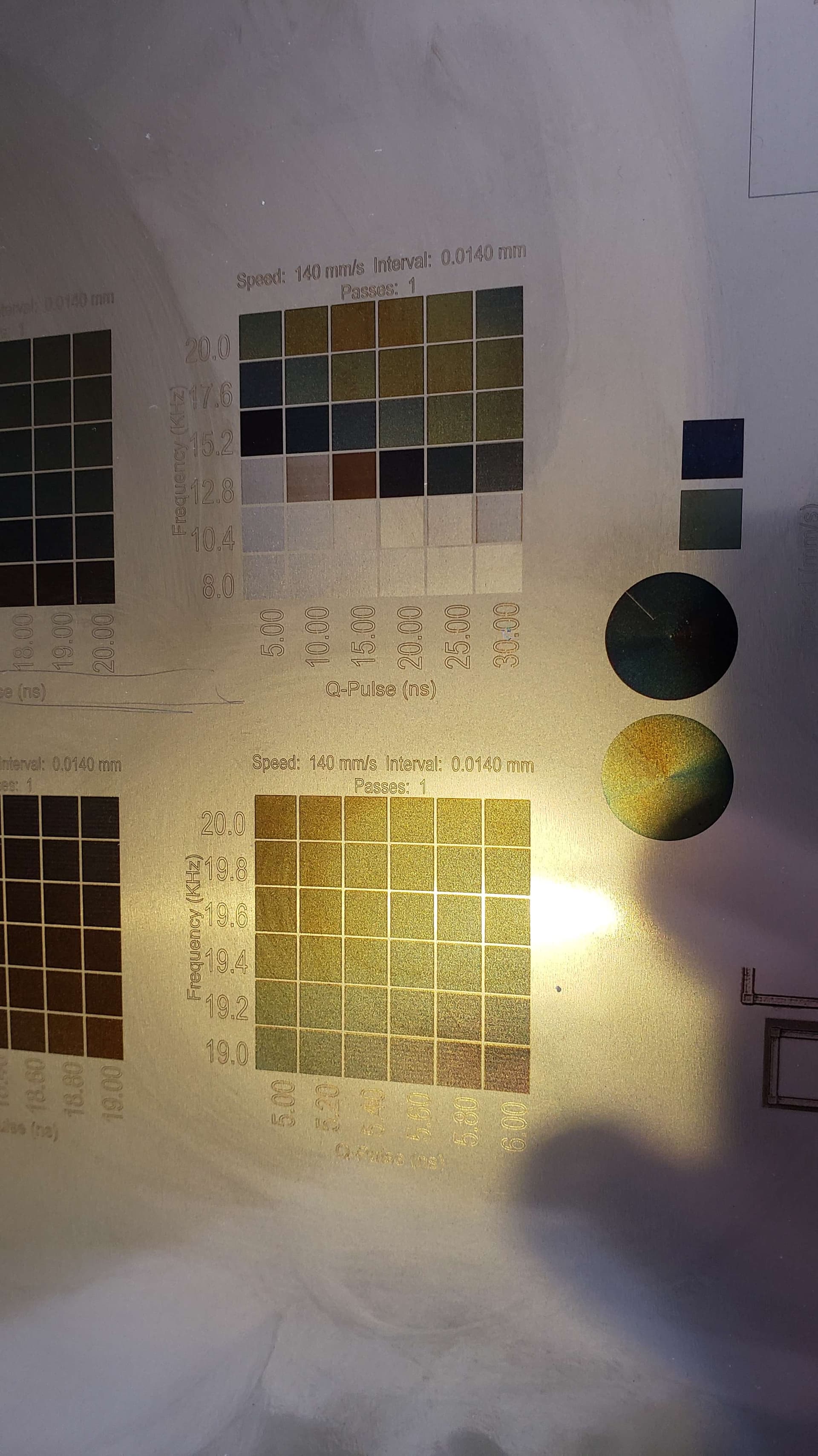
This is my fav palette that i have produced thus far. Very intricate colors in the 19-20 KHz @ 5-6ns range.
Even tho the photo may not be the best, it really looks like a continuous stable flow of colors.
I cannot wait to do some tests today with lightly dithering an image over a colored surface
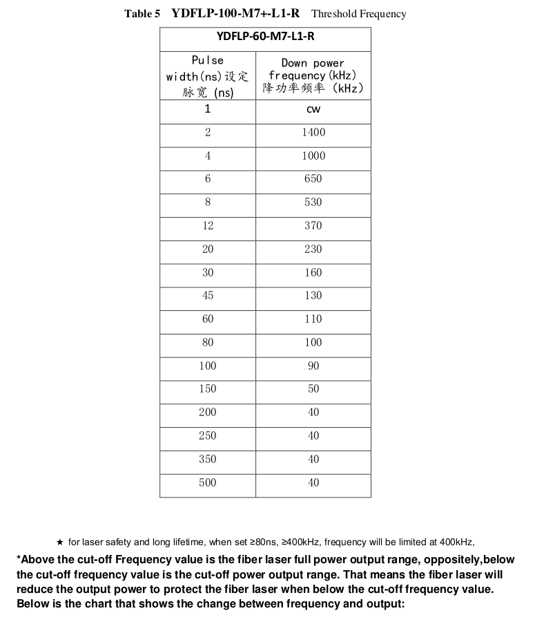
Fiber lasers take time to pump up the fiber. If your q-pulse is longer, the machine can’t pump the fiber up to the same level of energy. You get the most power out when the fiber is fully pumped and you allow it do discharge completely. The longer the q-pulse the more drain of the fibers energy.
I don’t know about your source, but mine has specific limits (threshold frequency) where for certain q-pulse widths related to frequency where you get full power. Longer q-pulse the lower the frequency threshold.
If you double your q-pulse width and the frequency is too high, it won’t produce the same amount of power.
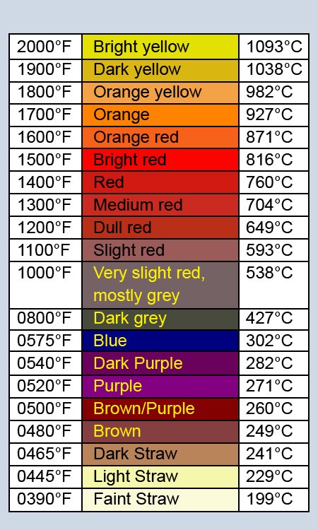
Hey Jack.. That looks a lot like the chart from my blacksmithing class.
We were hammer-welding at Bright Yellow with Boron flux to get the higher carbon stuff to stick together.
1333 F is where mild or carbon steel changes phase and a magnet stops sticking. Just over that is when you quench to harden mid or high carbon steel. Any hotter and the carbon starts to disperse out. That’s the Quench part of Quench and Temper. We made 3LB cross peen hammers.
We also tempered the hammer heads we made by making a hot spot in the eye of the hammer head. After the best guess, the heat source is removed and then we waited for the heat to conduct through the core and the hammer face to turn purple to blue to do the final quench. This is the tempering part that takes the brittle hardness out of the core..
I’m fairly sure this is a chart of the observed colors of the hot steel, not the finished oxide.
I’d love to be wrong about this so if you’ve got a reference or a source I’d love to know more.
One of the reasons I don’t always believe what I find on the Internet. Not having a way to actually measure it, it’s difficult.
I have seen a very similar one on tempering different metals. I’ve seen similar colors for tempering different types of iron.
I know I got this one from an article on lasing stainless for color and it was supposed to be stainless … However, I didn’t check credentials any further and I’ve lost that link
Maybe it’s the same idea…? Beats me …
I remember using this and needed a slightly different color. Thinking I was increasing heat, it did go in the right color direction.
Here, I’m pretty much guessing and using what has happened to me with it…
I second this, it can be quite difficult to replicate your results in stainless. You have to make sure the metal stays the same temperature each time or your results will vary.
I know that.
The average user has no idea of that and rarely knows how to create the ideal conditions to keep the “variable factors” stable.
In order not to repeat what Mickey had mentioned, I mentioned him for this purpose.
Hi guys
As you are using same machine as me, Omni 1 UV 5W, so you can share some details about it with me.do I have to set focal length each time I engrave some thing or how does it work. Does it depends on the height of material I am engraving or what. Also the parameters commarker has provided says line distance and hatch angle, but on lightburn there’s no such option to adjust line distance and hatch angle. Please help me on my this very new laser journey.
I do not use the same machine as you but think I can relate the general idea to you.
Whichever machine is used is most effective when raised a certain distance above the material that is to be engraved or cut.
The laser module is usually fitted with a measuring tool that is lowered to meet the surface of the material and then the mechanism or screws are tightened to secure the laserhead at that specific distance from the material.
Some manufacturers supply a piece of material of the correct thickness that is placed on the surface of the laserable material and the laser module is brought to rest on top of that, the securing method is tightened and the mesuring tool is then removed and the laser is similarly held securely at the correct distance above the laserable material.
You do not need to adjust this distance every time, but only check it periodically to ensure the optimum height above material is maintained.
The material should always be flat and level always.
Under some circumstances the laser module can be raised or lowered slightly but you can read about that when you are familiar with the basics.
Line distance may be referring to ‘Line Interval’ which you will find in the ‘Cut settings editor’. This allows you to set the distance between engraved lines.
I think ‘Hatch angle’ in lightburn is actually called ‘Scan angle’ and is also found in cut settings editor.
You may also select ‘Cross-Hatch’ which will scan at 45deg from Top-Right to Bottom-Left for example, and then repeat the process from Top-Left to Bottom-Right .