I’m trying to use the Material Test on Cerakoted stainless steel. The main screen shows the parameters I set, but when I open the bottom three boxes, it shows different settings .How does that work?
Also, in the two tests I’ve done, none of the squares are filled in. Aren’t some of them supposed to be?
I’ve read the documentation on iy but can’t find the answers.
Thanks.
1 Like
Main screen determines what you are attempting to vary in the test.
Since you can’t vary more than two settings, the other settings come from the Edit material settings tab.
Center tab, Edit Text Settings, defines the settings for the text only.
Lastly is the boarder. It works like the other two, just on the boarder.. I don’t use this option on mine. Seems to me a waste of material… but it’s likely just in my head.
Make sense?
If all else fails, read the documentation.
You need to use the fill option to get the object to fill the box. Accessing these start around 3:20 into the video.
![]()
1 Like
Thank you. That explains a few things.
I did read the docs but I couldn’t find the answer. I’m not much of a video learner (I’m hearing impaired, so I keep backing up and backing up) and prefer the written word.
1 Like
Don’t worry, we can probably help you out if you have issues or questions, so sing out if need be.
Take care
![]()
Will do, thanks.
I’m trying to engrave a flat black piece of stainless steel and can’t find a setting that looks good. Most come out pink-ish. I would love to get white but that’s obviously not possible.
This is in my library for white on stainless steel. if you have enough material, give it a shot.

I have a 60W MOPA.
Have fun
![]()
2 Likes
Is that white on bare SS?
I have a 50W fiber. 110 & 200 lenses.
Yes, I don’t have any black anodized aluminum. I’d think it should remove it… but I don’t know.
I think I used the F254mm lens at the time.
![]()
I tried it on bare SS (couldn’t see it) and Cerakoted flat black but no luck. I also tried various adjustments to your settings and still no luck. Seemed to just burn marks.
Thanks anyway.
I thought Cerakoate was a ceramic coating? I’ve seen Youtube videos of people removing it from things such as firearms.
Size of object has an impact on these. The longer it takes scan lines to complete the more heat is lost through thermal dissipation, so it won’t mark the same. I have a couple images I’ve worked with, one, smaller renders the colors correctly, the larger one … I’m still working on.
I’d expect to have to slow it down, speed it up or something to make up for the 20% difference in power. Also spot size of an F254mm is rather larger than your lenses.
That’s about all I can offer. The best way is to try and use the material test process to find a better value.
Good luck
![]()
Yes, it’s a ceramic coating. Comes in a bunch of colors.
I’m still working on settings without much luck.
I use a small scrolling design with the numbers underneath it for testing.
I’ll keep trying.
Thanks.
So you can burn colors onto the stainless?
That’s what I’m trying to find out and not having any luck.
Engraving on white looks nice, sort of brown-ish, but on flat black it looks muddied.
I’d like to figure out the settings for deep engraving on raw stainless.
Maybe I’m not following, but you have to remove the ceramic coating to get to the stainless.
So now I’m confused. ![]()
![]()
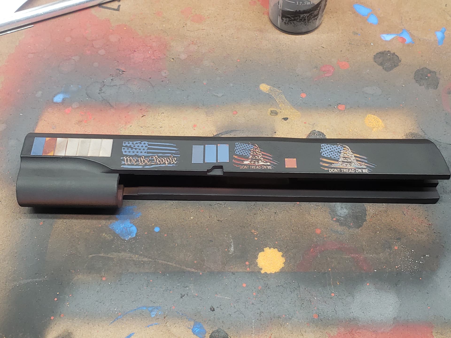
Cerakote removal works better on flat colors than glossy. Metallics the worse. But, it does work, need to experiment (A LOT) So example If I put a flat over a shiny, easy. If I put a metallic over a flat, very tough. Flat over stainless, low low power like 4%-12% 2 or 3 passes rotating angle increment.

Removing Graphite Black Cerakote from Gold Cerakote base layer

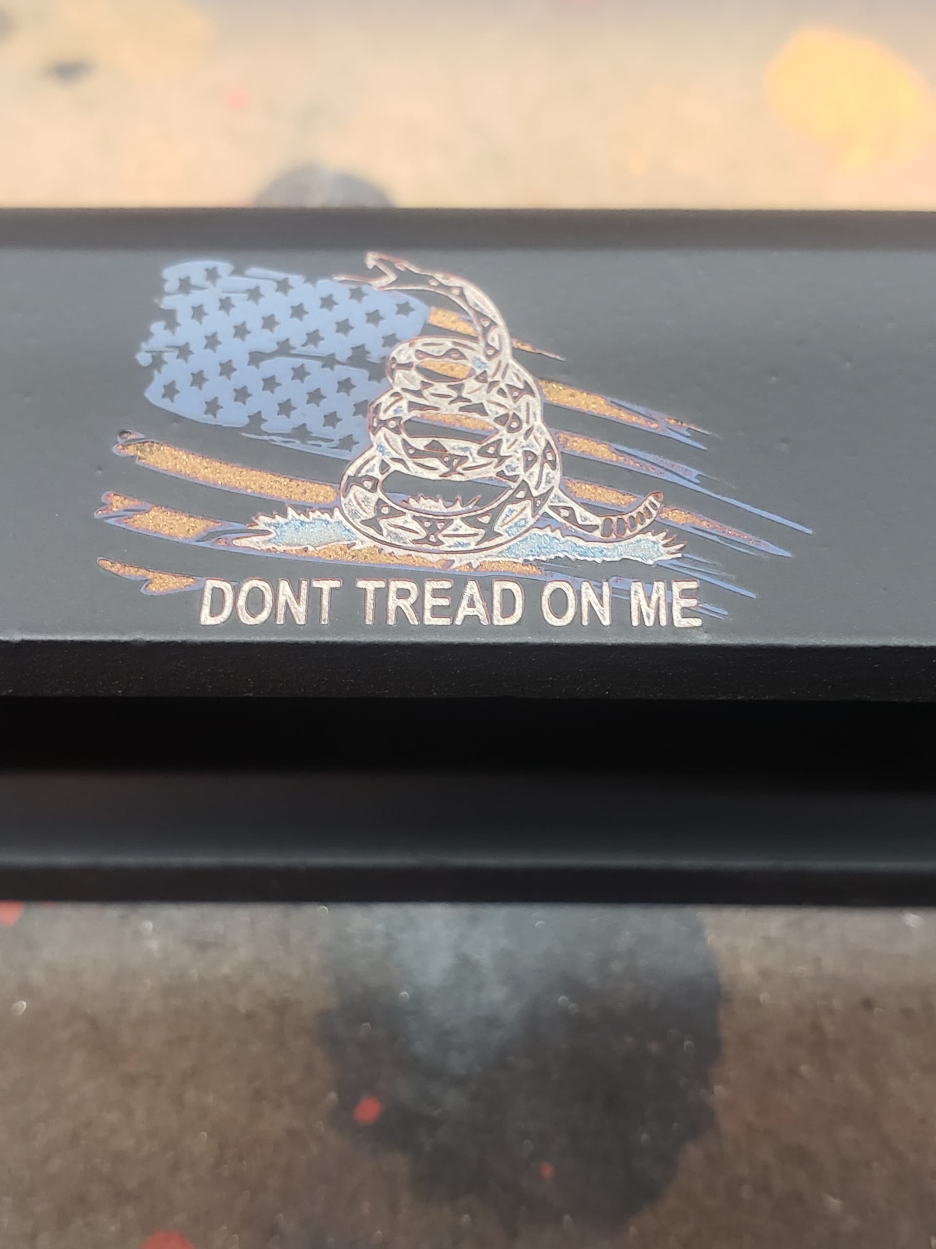
Removing several layers. Easy to get the Graphite Black Cerakote off, removing blue and leaving red a little tougher.
Ok, I’m working on a coated one but want to try plain stainless, as well.
I’ll be posting on the red light frame due to it being off after adjustments.
Thanks for all the info.
Could you explain the chart a little more? Like rotating angle increment? Then all the % numbers. You do all those in turn? Clock?
What machine are you using? I have a 50W fiber.
60W. Chart just an example of the different settings to remove different amounts of cerakote.
Angle increment changes the scan angle with each pass a set amount. Like if you had 3 passes set and used angle increment of 120, you would scan 0, 120, 240.
So red light framing has it’s own set of corrections. When framing the redlight uses those corrections, but when lasering the redlight follows the laser’s corrections.
I’m running a project now so I don’t want to start popping up windows but the redlight framing laser adjustments are in the machine settings I think
Galvo Framing - LightBurn Documentation.
Thanks and I’ve read that but it doesn’t say anything about it being off all the time. I’ve started a new post on it.