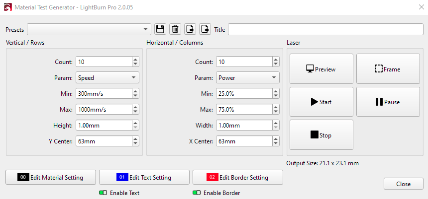
When running material tests on metal, in particular marine-grade stainless steel 2mm thick.
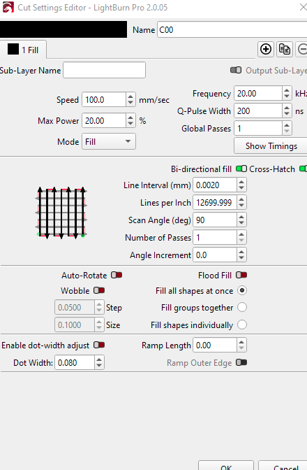
I set up a test as per the first screenshot below; however, the markings came out as outlines, so i went into the material settings as per the second screenshot below.
And I adjusted the mode to fill, ran it again, and it was very light.
So I went back into material settings and changed the line interval to 0.002mm and added the crosshatch, and it came out better and darker.
My question is, when running these tests, obviously the material setting is having an effect on the outcome, but are the test settings in the material test generator (on the first screenshot below) then overriding the chosen test parameter, so in my case, although in the material setting the Speed is set to 100mm/sec and the power is set to 20%, these numbers wil be ignored and replaced by the set parameters in the previouse screen on the material test generator.
And this will be the same for any of the parameters I set.
And everything else in the material setting screen will run as per the settings in the material screen (second screenshot below)
Also, I see there are buttons for “edit text setting” and “edit border setting.” How do these affect the text squares in the material generator?
or are these controlling the text in the results scale, showing what the grid means? i.e the chart axis labels?
And the border setting is just the square frame that is around the results given? Which I can turn on and off if I want to?
The edit material settings set the parameters you are not varying. e.g. in this case, everything that isn’t speed and power. The varied parameters will override these in the text squares. Edit text settings sets the laser settings for the info/axis around the material display. Border settings is indeed the square around the whole test.
I’d recommend you start with a fixed power of ~80%, as on a MOPA, power somewhat counterintuitively doesn’t have the highest influence on actual laser energy deposited. I’d start with an frequency/speed test first, then start tweaking interval and power. Changing q-pulse moves the frequency/power sweet spot for a given target significantly, so I’d consider that as one of the parameters to stay fixed across a test run.
If you put your exact laser in your profile it will help with future advice; e.g. for a certain 20w mopa, 200ns q pulse may be the sweet spot for getting the absolute max power out of it and 20khz; a 100w mopa may be at 450ns an 50khz. Running them both at this hypothetical sweet spot would require a lot faster scan speed, and potentially a lower interval with the 100w Vs the 20w.
When you get to trying to achieve consistent colour marking, you will learn to love/hate the material test. If you have a stack of 100 stainless steel cards now, order 200 more!
thankyou.
I am using a 200watt commarker mopa fibre laser. once i get near the colour i want am I correct in thinking that i need to de-focus in the upward directione by 2 to 10mm to get a nice black etching?
That’s not something I would recommend at all; I have heard of defocussing in some CO2 contexts, but in this case it’s completely the wrong thing to do. the actual depth of focus is nearer 0.5mm; defocusing by 4x-20x the focal range will get you no marking whatsoever.
When you get near the colour you want, you can tweak various parameters to get closer, and then just use those settings!
The thing I noticed is the distance per pass is set to ,002mm (over 12,000 passes per inch. The statement of wanting to do it in as short a time as possible is curious, What am I missing?