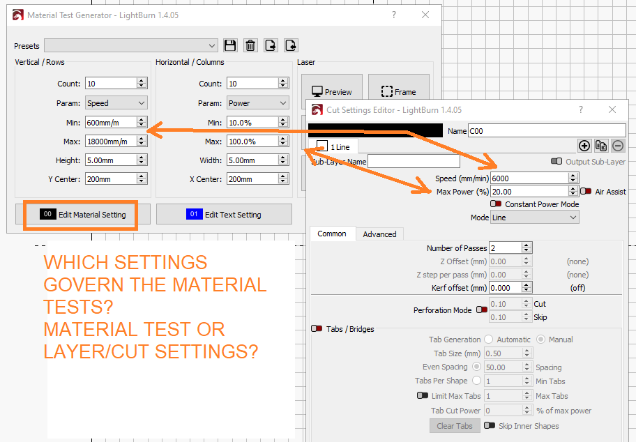
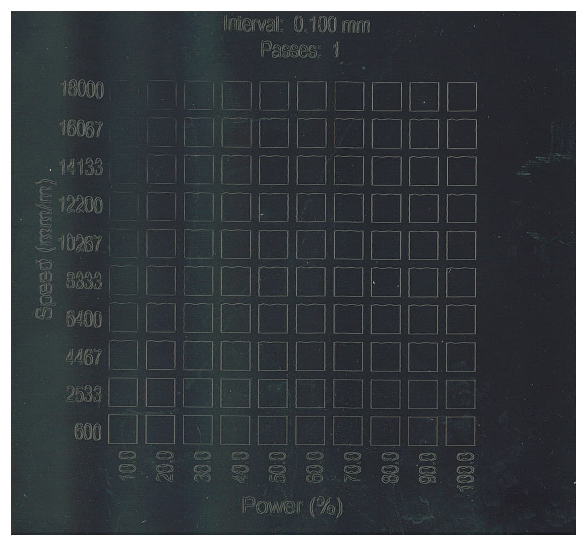
Material is Black Anodized Aluminum sheet. Varying from 600-6000mm/min and 10-100% power. It is almost as if the power maxes out really early. Then the machine outruns the laser.
If you have nothing selected in the workspace, the Cuts/Layers window is not used. The Material Test alone determines the Gcode sent to the laser.
Galvo is a different kind of machine that lases at different frequencies. The Diode cannot reproduce what he Galvo does. The only way to get various degrees of shading in a burn is to use dithering of some sort. A visible light diode laser performs very poorly on bare aluminum. Once you burn away the coating, that is what you have left.
Another way of saying what happens is that you burned through the anodize at lower power levels and increased power made no difference.
I edited my post to inlcude the images inline. Hopefully it is easier to see.
(Yes, the belts needed tweaking, I fixed that).
I understand that we have to experiement and adjust settings to tweak the output, but I feel like I am not even close enough for tweaking.
I was not sure if the Material Tests completely over-rode everthing or not. Its unclear from the documentation. Thanks for the clarification.
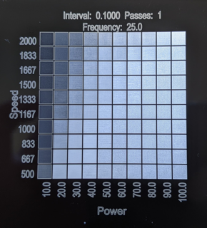
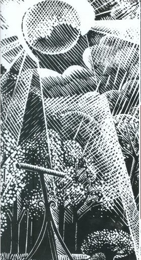
Comparing to galvo output: understanding that its a totally different machine and I should not expect the same quality of results, but won’t the wizard tests show a similar gradient of variation?
Anodize thickness and power levels: What should my expectations be for this?
Are we shooting for a varying gradient of half-tone accomplished by line width and spacing to created a density of clean/anodized regions?
Is it more of a scrubbing effect- cleaning off the anodizing?
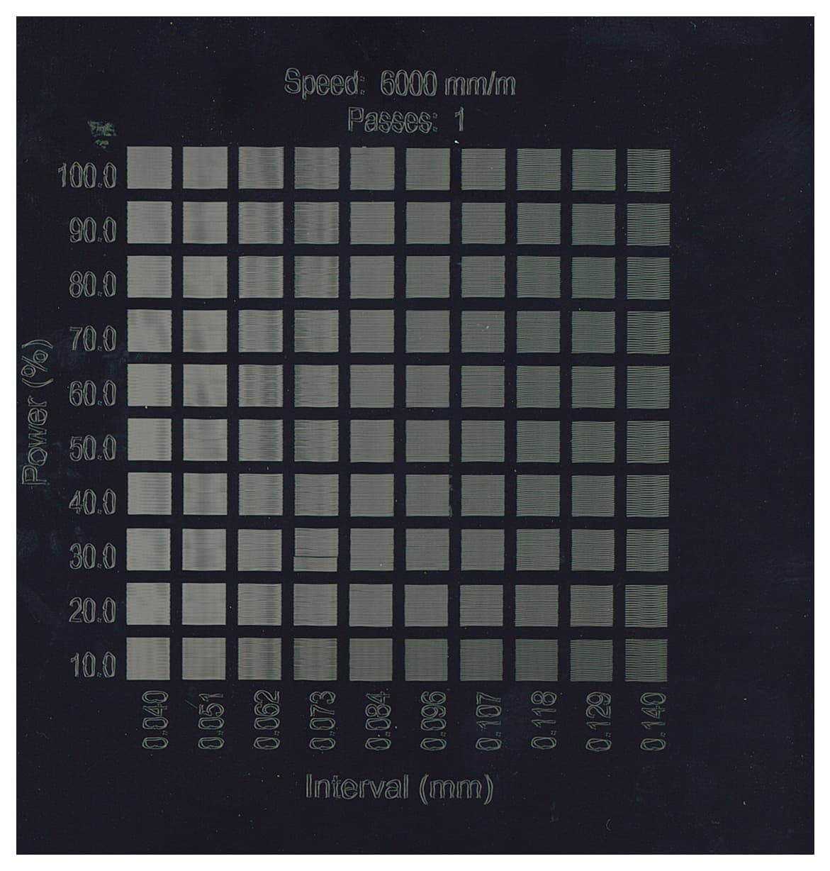
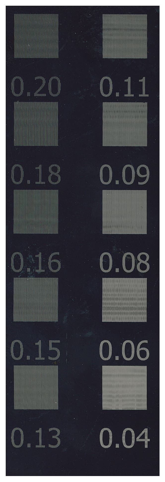
This is my interval test for example-from0.04 to 0.20 the effect is very much apparent.
I cannot help you here. Other than a couple of experiments, I do not do any laser work on anodized.
Think of as more like a machine gun effect. The laser vaporizes a spot, then moves on to the next. How much damage is done depends on the cumlative heat (power and speed). To vaporize more or less anodize coating would take some seriously fine control.
I think I read somewhere that you use image and not line on a rotary, where anodized mugs are popular. I do not know what your project looks like, but you might try using image thinking rather than filled lines.
By the way, in that galvo image, none of the squares match the surrounding black. What you see is what the galvo actually did to the aluminum.
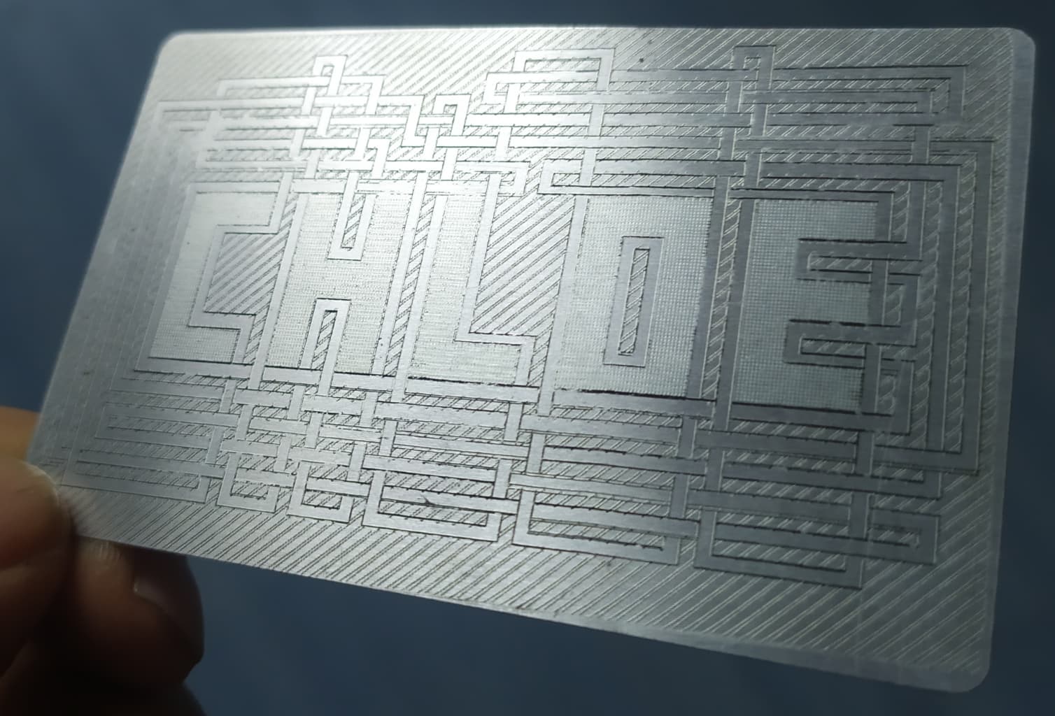
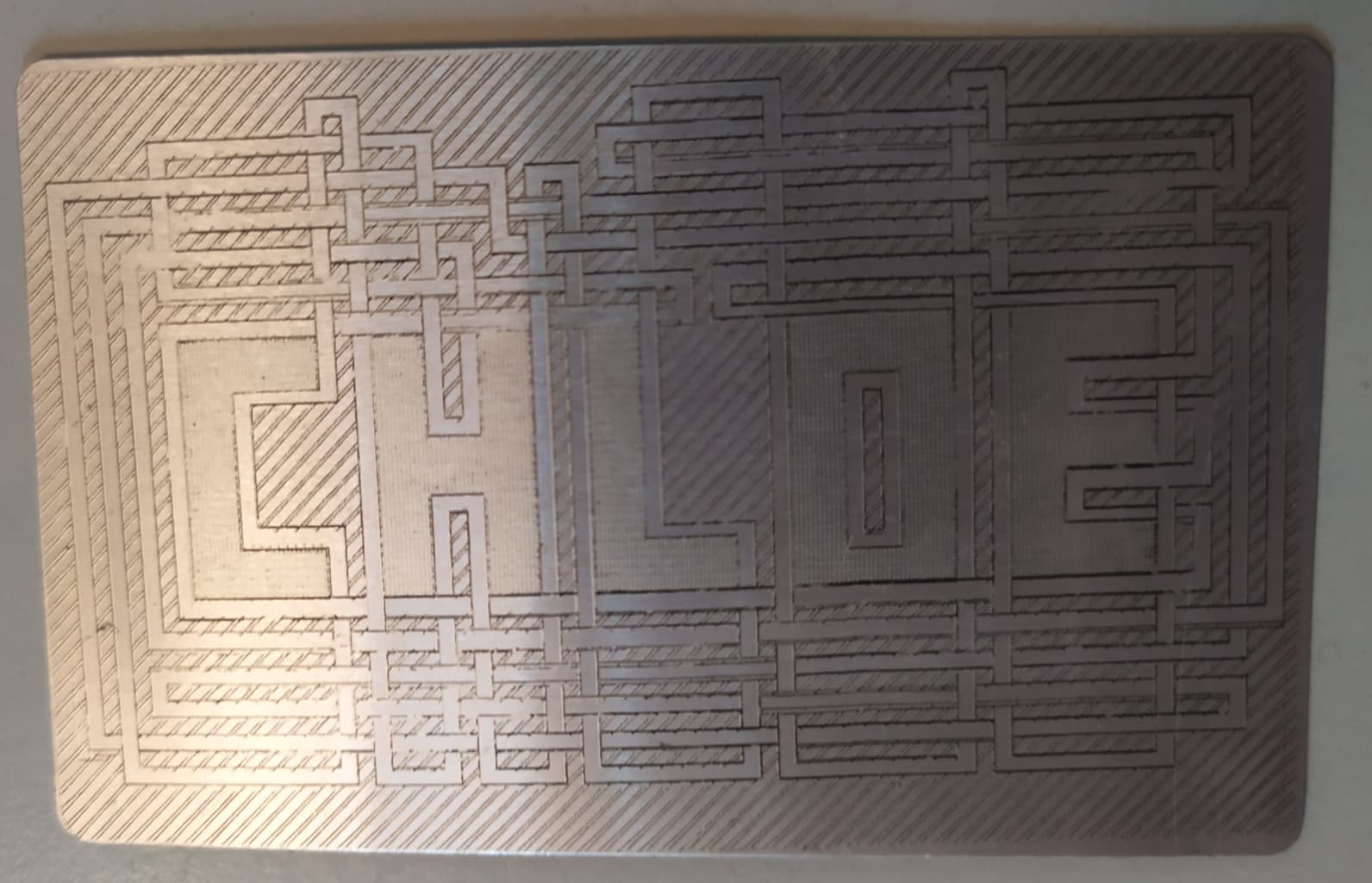
I tried to make a design on small raw thin aluminum cards, after applying a black coating or masking with tape, and the results were a bit disappointing once I removed the coasting / tape. I think it partially marked the metal (I can see some bumps on the other side), and part of the contrast might come from remaining masking material…
I used only line mode, not even sure what the result can be in fill mode.
I finally left the coating on, the contrast was better.
As said, not sure variations of power can do much result with diode, dithering a picture might give better results. Of course, as always, experiments are the key.
Most reasonable expectation is to consider the coating removal binary (present or absent) with shading accomplished by using a halftone effect.
In theory, a true grayscale is possible but the finesse required is such that it’s not very practical or repeatable. The difference between “white” (bare aluminum) and 50% gray is measured in nanometers…or less…change in coating thickness.
Your interval tests show pretty much as expected.
Approx .1mm shows total removal of the coating. Closer than this (smaller interval) shows very little change because your beam is about .1mm wide…ie, at closer intervals, you’re lasing the same areas more than once and a diode laser can’t really damage bare aluminum other than warping it. Above .1mm interval you begin to see shading as a series of black and “white” stripes. The wider the spacing, the darker the shade.
This was done with two layers (both vector) set to the same speed & power, but text @ .09 interval and leaf at .25 interval. It is intentionally subtle.
I don’t know if everything was clear now, I just wanted to mention that your first material tests look awful because the settings were far off. You tested 600-18,000 mm/min where the S9 is ony able to go at 6000mm/min maximum. And those 6000 are a theoretical maximum, the true maximum of the S9 frame is about 3000mm/min. So if you do a material test, stay below 3000 mm/min.
I have no scientific tests in this case I used the S9 back in the days and this was my experience. And during the past three years of user support mainly on Facebook, I could prove that statement to be correct in most cases
It doesn’t mean you can’t run it faster, but it needs careful tuning and a lot of experience to reach the top speeds with decent quality. 3000 mm/min is the average maximum speed of an average S9
Yeah, my S30 is rated for 6000mm/min, but I don’t expect to get that except maybe in a front to back run. Does not matter anyhow. That would be 3.8 seconds and I am not that good with a stopwatch.
I just read a bit about a 7.5w output blue laser, so it appears they have not topped out yet. 7.5 x 4 = 30w light output. that takes it from 20w to a possible 30w now. Invest in heat sinks for the future!