Doing a search on material test material thickness, there doesn’t seem to be a definitive answer. Is there a way to set the material thickness in a material test? I saw where layer 00 was the answer, but when you start a material test there is no layer 00.
Also, where does lightburn get the starting coordinates for the material test? I have mine set at absolute coords with bottom left selected. This seems to yield random results. If I select user origin or current position, I don’t get the desired results either.
I would ideally like to set the material thickness, hit start, and have my laser start at 0,0 (or bottom left).
Not sure what you want to do or accomplish. The controller has no idea of what kind of laser you have, if cutting steel or paper.
If you could enter thickness, you’d have to take into account the type of material. Both Lightburn and the controller have no way to use this kind of information without guessing on the other parameters.
You only have two places to adjust the operation, which is speed and power.
Even I have to start at known values and test them when I do a different material or a different batch.
Maybe if you took a little more time and explain it, I may not be following you.
Of course this is relative to 0, 0 of my origin or?
If in doubt, go to the docs and enter it as a search.
First thank you so much for taking time to respond. I really hope we can decipher this issue…
This shouldn’t matter… I’m interested in setting material thickness. It doesn’t matter if it is steel, paper, or insert whatever material here. What matters is that non-autofocusing lasers need a way to determine how thick a material is. Even when you set up layers in lightburn, it asks you for material thickness in your layer parameters. Why doesn’t this same parameter exist for the built in material test? For instance, I have a 4 inch thick piece of maple that I’d like to run the test on… Without telling my laser that the material is 4 inches thick, the laser will crash into the object. Again, this parameter DOES exist on engraving/cutting layers, just not on the material test as far as I can see.
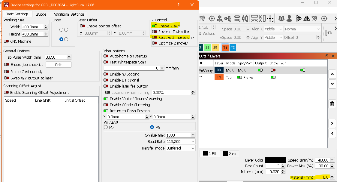
The image below shows the parameter I’m looking for in the material test. This is just a layer that I added to a blank document. I’ve seen others comment in the past that this layer material thickness is used for material tests, but in order to even make it active, you have to create a layer in a blank project. So I’m not sure if this is what people are suggesting. I just don’t want to damage my laser.
Jack, I’m starting to question my workflow. Let me walk you through it. It might be totally wonky.
So first of all, I have a Snapmaker with 40w laser. I’m looking at getting a different laser down the road, but right now that’s what i’m using. I’ve set up the laser in lightburn for full control. It has been calibrated to my laser to the point where when I do a project, I only have to work on design, put in material and material thickness, and hit run. I don’t have to focus, calibrate, or move origin as everything is automatic.
That’s why I’m having issues, I’m used to the software and machine doing everything for me. Maybe that’s the wrong way to go. Should I be setting X,Y, and Z for every project including Material Tests? Seems like extra work, but if that’s what others are doing, maybe there’s a reason.
If you do not have AutoFocus, then you do have to do this. You use a bar or shim gauge to set the laser module height above the material. If you do have AutoFocus and it is wonky, that is a machine issue, not Lightburn.
My question to you is why is this necessary? I’ve focused/calibrated my laser to the the bed of the laser which is level and true. That measurement should never ever change. Now when I go to use my laser all I should have to do is put in material thickness and it should be focused to the correct height. This has been true with everything within Lightburn except for the material test dialog. I’m trying to figure out what Lightburn is or isn’t doing that I am expecting.
I’m thinking of just giving in and focusing/moving my laser for every burn, but ideally I would like it automated so it cuts down on time. Especially with multiple runs.
I do not have a motorized bed, so please help me understand.
At what point in the process do you make this setting? I would think you need to do this before loading your material onto the laser bed. For example, if your prior cut was on 3mm wood and your next job is on 38mm lumber, you would likely need to lower your bed for laser head clearance before loading it, correct?
If this is the case, set your bed height / material thickness, then go to the material test. It should not change the height again at this point, does it?
Are you talking about doing multiple material tests back to back with different materials?
I do not either. Is this for the Snapmaker A350T machine. That one does not have a lifting bed. I uses Zaxis travel with a fixed bed height, so the focal point height will always be shifting with the material thickness.
If we have the wrong machine, please update your bio.
Gentlemen, please let me first start of by saying I’m sorry. I think I’m confusing everyone with what I’m expecting and I think we got away from the actual issue. So, first, yes I’m using a Snapmaker A350T. I have followed someone else’s tutorial on how to set it up to be full control under Lightburn. Everything works as expected from the software except for the Material Tests.
My bed does not raise or lower. The laser itself raises and lowers to the bed. The “Start GCode” as defined under the device settings basically homes my laser, then lowers the laser to the 0,0 coordinate based on the material thickness. So if I was to engrave my bed, I would leave material thickness at 0mm.
When creating a layer in Lightburn, one of the variables requested is material thickness. So Lightburn makes the calculation based on my Start GCode which is constant to my machine and subtracts the height of the material to get the Z height of my laser. This is done automatically based on settings alone and not by me lowering, raising, or manipulating the laser in any way. When using a known material, all I have to do is create a layer in Lightburn, tie that layer to the known material, tell Lightburn it’s 3mm thick. Then hit start. My Start GCode will home the laser, lower the laser, and start the job at my laser’s origin which is set to absolute coordinates of 0,0. This works 100% and is accurate. I’ve never run into an issue until I started using the Material Test dialog.
So I want to start engraving a new material and want to run material tests. I create my test, set up all the parameter within the Test Material dialog. Put the material into my laser at 0,0. Hit run and I get random results. So the Material Test dialog is doing something that normal Lightburn is not. I’m trying to figure it out, but I’m having issues. One obvious omission is that there is no material thickness in Material Test dialog. The other is that absolute coords are not working the same within Material Test dialog as it is on regular Lightburn layers.
So that’s where we are. I hope that answered some questions and hopefully didn’t confuse you more. However, if it did, please let me know. I genuinely would love to figure this out. I would also like to determine if my whole work flow is flawed and I should be doing this all manually all the time.
OK, I believe I understand the process now. What happens if you make a square, or any shape in Lightburn, assign it to the black layer, set your material thickness on the black layer, then go to the Material Test? Would that work?
The material test centers the test in the workspace by default when using Absolute Coordinates. You can change the location of it with the X Center and Y Center dialogs. You can also choose User Origin or Current Position from the Laser Window before going to the Laser tools Dialog and it will use those start modes.
Haven’t tried this yet. It could be a good work around. I’ll try that next time I’m out in the shop.
Understood, but that only centers it within the test area. It doesn’t have anything to do with work surface as far as I’ve experienced. What i would expect is to set the center as you stated, hit start, then the test would start engraving at 0,0 assuming I calculated center correctly. But what happens is totally random, or i haven’t figured out what’s actually happening. One time it does the test in the middle of my work area, another time on the far right side of work area, another time it went out of bounds of the front of work area. It never has come close to starting at 0,0.
So test materials is overwriting my absolute coords as defined in gcode or not using them at all.
I was in absolute coordinates when I took this screenshot. If you look at the coordinates, that is the center of my 500 x 700 bed and the test pattern centers on that location. It does not go to a 0,0 origin point. It would be nice if you could set a 0,0, but the manual adjustment is for “center” of the test pattern, not a corner. You can adjust these settings to get it closer to a corner, but without knowing the dimensions of the test you can’t get it exact. I usually hit the frame button and place my workpiece appropriately. I also have my system set to frame continuously when adjusting things manually.
If I choose one of the other Start From modes, those settings are grayed out and it uses the 9 dot job origin along with the set origin point, or current position if you choose that mode.
The test runs the text layer first, then the engrave or cut, then the border if enabled.
Not sure when that was added, I only noticed it about 2 updates back, I don’t think it was originally there, but might have been and I just hadn’t noticed it either.