Hi Guys, just installed V1.4.04 (I have a Gwieke Cloud laser) and noticed then when using the material thickness setting (17mm minus the material thickeness = what you put in) did not work and laser head was way too high and unfocussed. After testing and fiddling I just put in the material thickness i.e. 3mm and it worked. So have lightburn changed this in V1.4.04. Hope so as this makes way more sense … or do I not know what I am doing ??Any thoughts
From the 1.4.04 release notes at LightBurn 1.4.04 - Patch release / bug fixes – LightBurn Software
“Added detection of G-Weike Cloud laser, handles Z correctly now (auto sets proper Z height based on material thickness)”
Sounds like great news! I will soon update to 1.4.04 on our Gweike Cloud laser and try it. Are you experiencing any issues with it, or was it just a surprise?
Hi krono, thanks for the reply. iIhave now read the release notes and that makes sense. thanks for the feedback. No problems with it at all - I was just surprised. Works like a charm and much simpler (less brain space needed),
Kind Regards
Glad to hear it. As of 1.4.04 it’s a matter of Enabling Z-Axis, turning off Relative Z Moves, setting the material thickness in the Cut Settings Editor and you’re good to go.
The material thickness / focal distance settings for the xTool P2, Omtech Polar and Monport Onyx are pending.
Hi,
I recently updated Lightburn to 1.4.04 and found, of course, the change regarding the Z-Axis settings on Gweike Cloud machine as I am using one. So, a big “thank you” for this improvement, which make life more easy!!!
But… there is one point I would like to verify in regard of this change:
- between 0.1 and 16.9 mm material thickness everything looks to work fine. The “17mm - material thickness” - rule of Gweike seems to be implemented well.
but: - I found a problem with thickness values of 0 (zero), where Lightburn sets the Z-Axis to 0 (zero) instead of 17mm. So far I didn’t try to set negative values to set the Z-axis toward the max. of 25mm which is the maximum range on this machine.
- I found also a problem with thickness values of 17mm and more, where Lightburn sets the Z-axis to the maximum of 25mm instead of 0mm.
Could you please verify this finding and tell me, I am right or wrong. If I am right, I would welcome a fix in 1.4.05 ;-)).
Regards, Ekkes.
This is likely because they didnt realize the gweike cloud, omtech polar, and onyx use negative z values
There is another set of information that we’ll need to confirm here.
Please click Edit, then Device Settings (toward the bottom of the list). Toward the top of the Device Settings window, there’s a Z-Control window with three switches.
- Enable Z axis (It’s probably on, as it should be)
- Relative Z moves only (now off for 1.4.04)
- Optimize Z moves (on - but I’ll double check this)
Please let me know what you’re using for 1.4.04
Thanks.
I am using Lightburn 1.4.04 whith my Gweike Cloud Pro (the pro means with rotary device). The Gweike consists of a Ruida controller. I am not sure what type of Ruida is used.
To check the new material thickness calculation of Lightburn, I did the following steps:
- set Z control switches in the “device settings” menu to “Enable Z axis” = ON, “Relative Z moves only” = OFF, “Optimized Z moves” = ON
- set the materail thickness in the “Cuts/Layers” windows to 0, 0.1, 1, 16.9, 17 and 23mm
- start the job (just a circle in line mode) and pause it, when the laser starts to cut the circle.
- check the Z-axis position in using the “Get position” button of the “Move” window
- finsh the job and change the material thickness value
My observations are:
Mat. Thickness; Z-position (as shown in the “Move” window); expected Z-Position
0; 0 (wrong); 17
0.1; 16.9 (correct); 16.9
1; 16 (correct); 16
16.9; 0.1 (correct); 0.1
17; 25 (wrong); 0
23; 25 (wrong); 0 or error message as the max. thickness is 17mm
**** Unfortunately I had to reformat the table above. Because I didn’t found a way to format columns, I separated the single fields with “;” ****
These results have been identicial whit both possible settings of the “Optimized Z moves” ON and OFF.
Negative values of meterial thickness are not accepted by the input field of the “Cuts/Layers” windows, which is logical as there are no materials with negative thickness but this would be way to implement the Z-axis positions lower than 17mm.
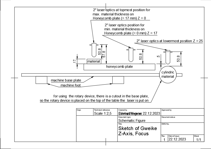
Z-axis positions > 17mm might be needed when using the rotary device, what is placed below the honeycomb table level.
To use the rotary device you have to redraw the honeycomb table and the floor tray of the Gweike laser cutter and place the rotary device inside a cut of in the machine base.
This can lead to a material top edge of less than 17mm.
The problem here is the definition of the Z-axis of the Gweike Cloud device.
As the topmost Z-axis position is defined as 0 (zero) and the lowermost Z-axis position is 25, the top edge of the honeycomd is located at 17mm and material placed in the rotary device might be lower than the honycomb, makes the handling not easy…
I hope I covered all information helpful for this topic. If there are any more questions please let me know. I am happy to provide them as I am able to.
I don’t have the Gweike Cloud here to test but Oz wrote:
- Added detection of G-Weike Cloud laser, handles Z correctly now (auto sets proper Z height based on material thickness)
I’m keen to have you try something (if you’re so inclined).
With your Gweike Cloud connected, click the Devices button in the Laser window. When the Devices window pops up, click Find My Laser.
You’re right about the Z-Axis being reversed. We’ve known about the Gweike Cloud having a reversed Z-Axis for a while. ![]() It may have been a matter of detecting the device as being different from the regular Ruida controller.
It may have been a matter of detecting the device as being different from the regular Ruida controller.
I tried to force LightBurn to build the profile manually but it wouldn’t.
I’m looking forward to seeing if the Auto-detect works.
I confirm the statement of Oz except the max./min. setting (0mm / 17mm). Also the remark from Mountaineer Tradepost is correct, as I tried to describe in my former postings.
Please find attached a screenshot of the “Find My Laser” result:
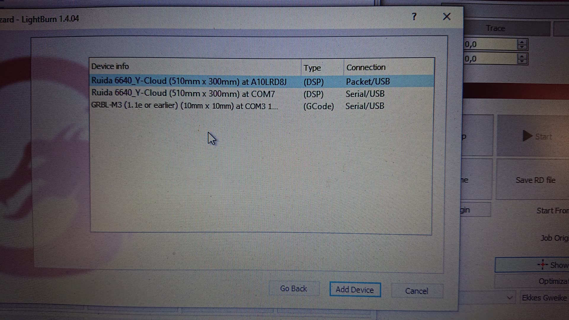
As you see this function detects three devices. The two upper ones are the devices created by the Gweike laser. I am able to use both without detecting any differences in functionality so far. For the third device I have no idea where this comes form…
Additional, where you don’t have a Gweike Cloud physically on hand, I thought you might have use of the Controller settings. Please find attached the export of the two uppermost devices of the list from the screenshot.
Ruida_6640_Y_A10LRD8J.lbdev (1,6 KB)
Ruida_6640_Y_COM7!.lbdev (1,6 KB)
If you need anything else, please let me know.
This is great news for sure. I am trying to get a Gweike cloud Pro 2 up and running, but the head keeps crashing into the honeycomb. I’m also a Lightburn newbie. I am using Lightburn 1.4.04.
After setting the material thickness what value do you enter for “Distance” in the move menu?
Do I still do the subtraction from 17?
Thanks
John
If you havent updated yet just use a negative z value for gweike cloud.
I am using Lightburn 1.4.04
Yes sorry I see that now. I should avoid replying at 1am. I hope you find a workable solution ![]()
I do a similar thing when I don’t wear my glasses.
No problem, I appreciate the help. Gweike has not been too great a help.
After setting the material thickness in the Layers and Cut what value do you enter for “Distance” in the Move menu?
Do you enter the material thickness or 0, or 17mm?