I am running an OMtech 130w laser with a Ruida 6442G controller and ZYE MYJG150W-1 laser power supply. The tube is rated for 30mA max , 80% level is then 24mA. When running I hit the 24 mA at 55% power as set in lightburn. 30 mA is at 65-70%. It will go higher still as the laser came with a 150w power supply. It would be nice to have the scaling in LB set so that 100% is 30mA so I do not inadvertently damage the tube.
There is apparently no max current trim pot on the laser supply (nothing note in the manual and nothing visible).
I have not yet double checked the current with a VOM.
In the LB Machine setttings → vendor settings, if you scroll down to the Laser Settings block there is a line for Laser 1 maximum power which is currently set at 98% (from the factory).
What exactly does this do? Is it a multiplier (e.g. lower setting lowers the max mA), a limit in the LB menu (simple number not to exceed in the layer parameters), or is it really a divisor (e.g. currently measured value is a percentage of max and could go above 100%)?
It would be nice to know the meaning before cutting in the line to insert a mA meter and then experimenting with the setting.
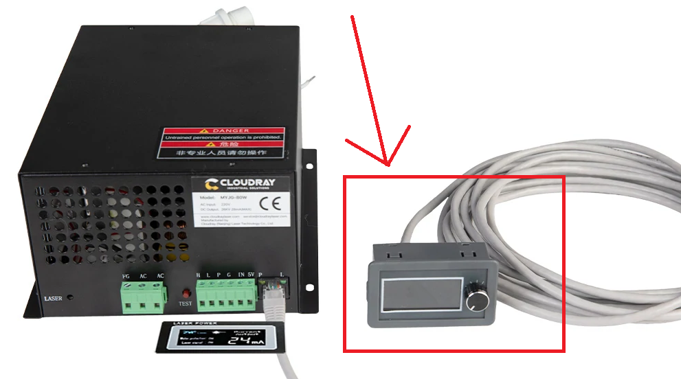
yes that appears to be the display that is used on the power supply on my laser. What I am trying to do is calibrate the mA output vs the % power in lightburn. With the 130w H6 tube I have, 100% should be 30mA. I hit that at 60-65%. However it can easily go higher, as when doing a power scale test (multiple lines at increasing power levels) I aborted the test when it hit 34mA (about 75 or 80% in LB). So I would like to have a way to set everything so that 100% in LB is 30mA or so.
A max power limit, scaled to 0-100%, from LightBurn itself will be very welcome with many users. I think this topic has been up here in the forum before but, the feature could not be implemented in LightBurn for “technical” reasons. (if I remember correctly!) There was always reference to the small potentiometer in the power supply itself which can adjust the output max. But not all power supplies have this function and I personally will never stick a piece of metal through a small hole in a high voltage power supply to, (without seeing anything what I am messing around with) adjust the output power.
I doubt if “Cloudray LCD Display Current Meter For MYJG 100W & 150W” can limit max power output in that it is not programmable. It is probably more intended to adjust the current output power in mA for the performing task with the laser, but the range is probably 1-99% of the power supply itself.
It might be worth checking. But the trim pot on my psu is not located under the hole marked laser. My trim pot is accessed thru a hole on the side of the power supply and its pretty easy to adjust if you have a meter installed.
Hello
I bought this controller to avoid putting a screwdriver in the hole given the price of this controller we gain in security
put the laser on 100% and turn the lever to bring the meter to 30ma
and here you have settled the 100%
My understanding is if you config the Ruida Laser 1 to 70% Max Power 5% Min Power, that becomes the base scale for all other %. The user’s “100%” physically becomes 70% at the tube supply.
When your Layer setting asks for 100% Max Power 0% Min Power, then the actual physical modulation given to the laser tube supply will start at 5% and go up to 70%.
If your Layer is 50% Max 10% Min power, then the actual tube drive sees 35% max 11.5% min. That last number is a bit complicated- the Ruida’s hardware-adjusted scale is 70% to 5%, or 65% of full scale + 5% of min as offset. 10% is 6.5% in that scale, plus the 5% of Ruida’s Min Power offset, equals 11.5% min power.
Min power begins once it is in a cut and Start Speed is exceeded. It won’t just keep firing at min power all the time.
So, yes, it’s a multiplier burned into the Ruida hardware. The user’s jobs will all be rescaled and limited by these parameters
If the laser is firing or on, it stays at Min power and will not increase until it passes the ‘Start Speed’.
His issue seems to be that the power is way high… I think I had a similar issue.
I have a 50 watt China Blue, it has a 60 watt supply which would easily drive my tube into the danger zone >21mA at over 85%. Max placard is 21mA.
Set the machine to 50% power and adjusted the lps for 11mA (about 1/2 of 21mA).
Ensure the Ruida is set for 9.4% (minimum lase) to 99%. My power scale is close and I can drive it hard if I wish.
The supply should be linear across the pwm range. The middle is a good place to test it… suspect you will be closer to the 50% power using the machine than the 100% power…
I ran a series of tests to see if I could use the min and max percentage levels to: 1. Safely limit the max current. 2. Rescale the % power settings so that in LB 100% would be 30mA.
I also wanted to verify that the mA indicated on the power supply display was accurate
I used a power line test card. It has a series of horizontal lines at increasing power levels form 10 to 85%.
I inserted a VOM into the DC return from the tube to the power supply . I used both an analog and digital true RMS reading VOM to cross check the accuracy. The displayed values are quite close. The values shown are truncated rather than rounded e.g. both 26.1 and 26.95 show as 26mA on the display.
Next I tackled the linearity and limiting. I had hopes based on prior replies that the max and min values could be used as gain and offset values for calibrating the percentage vs actual mA . It turns out that the max mA percentage instead acts as a “clamp” or limit. Rather than list the whole table I will use some example values In my case for example 40% is 17mA, 50% is 22mA, 60% is 26mA, 70% is 31mA and 75% is 33mA (after which I stopped due to being over the tube rating). If I set the max % to 70 then the max current (regardless of % form 71-100% ) is limited to 31mA and lower values are unchanged, if I set the max % to 50% then the current is limited to 22mA and all values above 50% are also 22mA. I settled on setting the max to 65% - 29mA. So at least the first and third goal was achieved in that I cannot accidentally exceed the max rating and I now know what the accuracy of the display is (-1.5 to +0mA of actual). Repeatability was within about 5% but I did not explore this deeply. This also means that my materials library is unaffected and I don’t need to repeat the growing pile of test cards for cutting and engraving.
I also explored the bottom end the tube will start to weakly lase at 8% drawing 0.5mA with 0 indicated on the display 9% is 1mA, 10% is 3mA (clearly non linear on the very bottom end. I did not bother to adjust the min % and will just continue using 10% in my LB min settings. However it is interesting to know that with a complex / dense line engraving I could go lower (but may have inconsistent results.
Thank you for the replies.