Maximum CO2 Galvo Bidirectional Raster Scanning Speed?

I would appreciate some feedback to anyone who currently owns a CO2 Galvo machine!

I have a CO2 gantry laser (and also a UV Galvo and Firber/MOPA Galvo) and I recently purchased a CO2 Galvo specifically for faster raster scanning (and to minimize all the side-to-side wear and tear on my gantry).

I even purchased an upgrade ($290) to a Galvo head capable of up to 7000mm/sec…

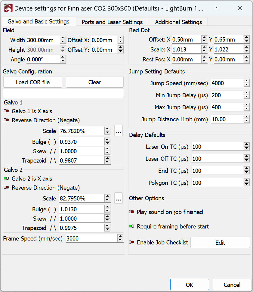
I can not get a proper raster image on this machine at virtually any reasonable speed. I have run tests at 5000, 3000, 2000, and even 1000 mm/sec.

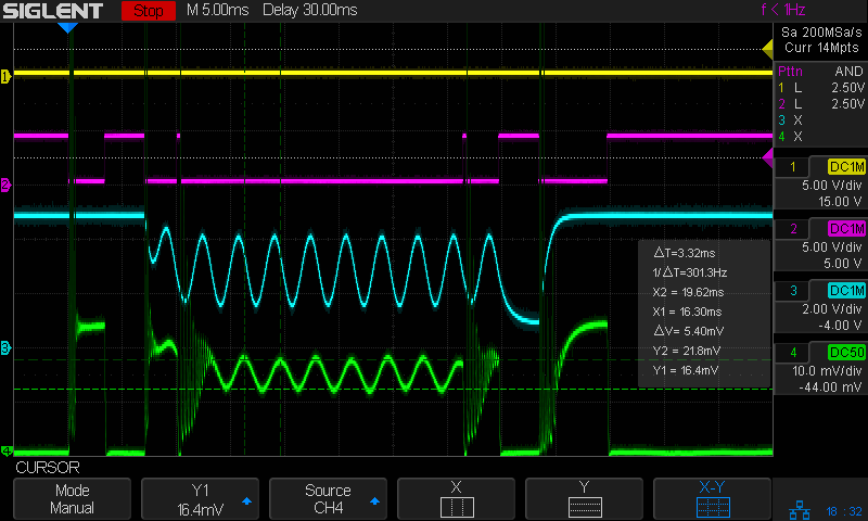
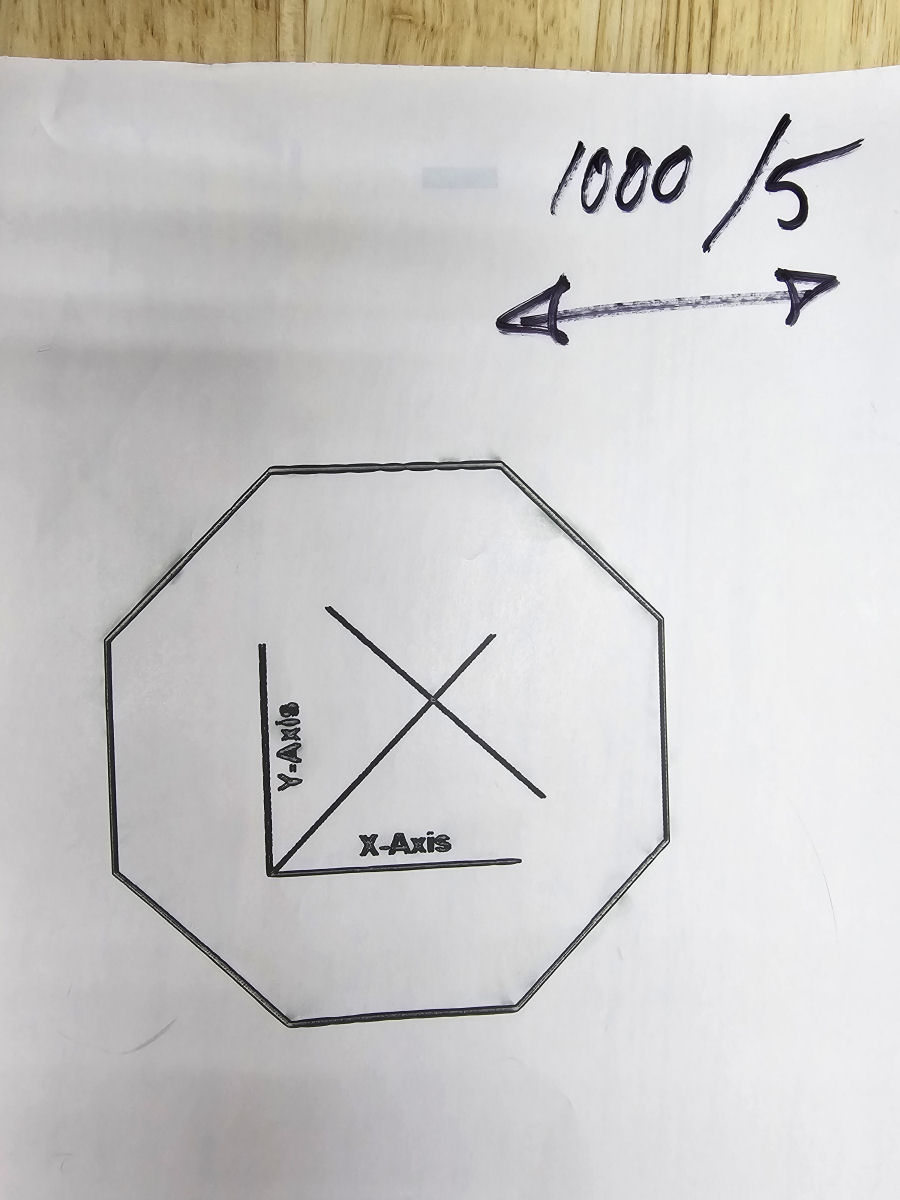
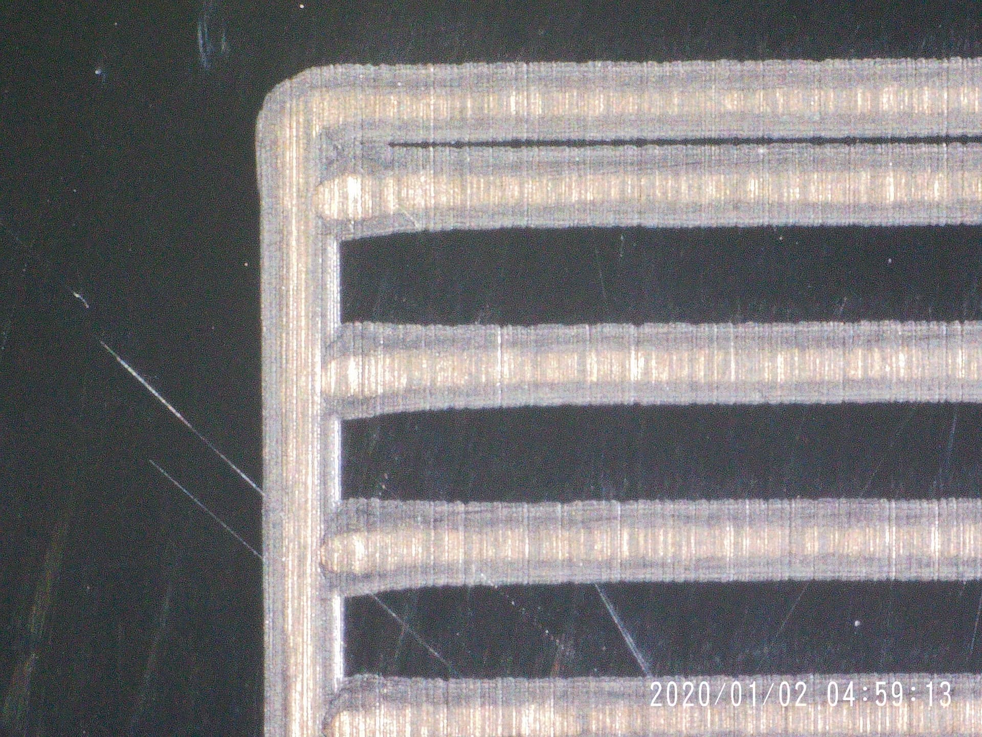
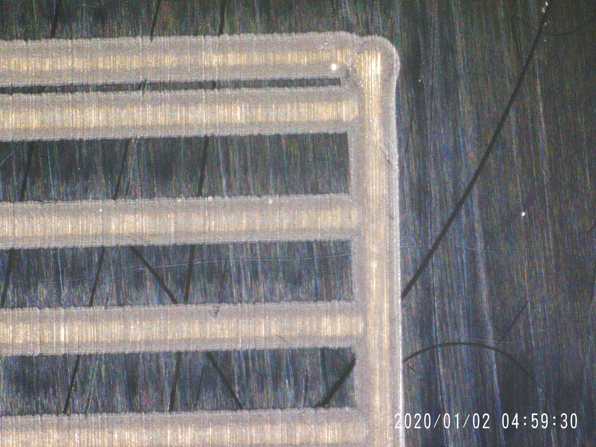
The manufacturer has participated in a Zoom call and even they could not get a proper image as low as 1000. (I was testing on thermal paper so we didn’t go lower as all it would do is burn). No matter what settings we/they tried, I always got a double (skewed image). Basically, the even number rows were pushed in one direction and the odd number rows were pushed in the other. In the end it looks like a double image. Its actually two half-images slightly apart.

The manufacturer is telling me that CO2 lasers are simply not capable of firing fast enough (turning on/off) to keep up with the galvo and that I will need to adjust my speeds lower than 1000 mm/sec. To me, this makes the purchase of a CO2 Galvo laser useless. I might as well use my gantry for such slow speeds…

I run my UV Galvo and Fiber Galvo at speeds greater than 1000 mm/sec all the time. It appears they are trying to tell me that a CO2 laser can not fire fast enough to run at these speeds.

I think they are just making excuses for a machine which is not properly designed. However, I would like to ask anyone with an actual working experience if they can tell me what the actual maximum biderectional raster scanning speeds their machine is capable of (without corrupting or distorting the image)

Anyone? (Thanks in advance!)

This could be timing on the start and end of the delay… This Laser Everything is done on a galvo fiber, but the mechanism is the same. You can watch it and see it it’s applicable.

Probably true if you want to actually control the tube. You can’t really compare ssl (solid state laser or diode) or fiber (also solid state) with a dc excited tube laser.

The response time for an lps, is usually <= 1mS… At worst case, running 1000mm/s you are covering 1mm in 1mS, the best resolution you can possibly get is 25.4 dpi/lpi.

If you drop it to 500mm/s, you can double it to 50.8 dpi/lpi… 250mm/s is 101.6 dpi…

Few gantry machines can reach that kind of speed.


I’d suspect that your issue is actually a combination of issues. This is my guess…

You can mitigate the response time issue to some extent. When you do something on a co2, for example a line @ 50% power… a dc excited tube can lase at 50% power, whereas a ssl cannot. It’s when you start en/disabling the lps that these delays occur. Such as with an image or dither …

I hope you follow me with the lps/tube response time explanation.

Good luck.

:smile_cat:

That is definitely true of “ordinary” DC-excited CO₂ tubes & power supplies in cheap gantry machines. RF-excited CO₂ tubes have much faster response times, but I don’t know whether that’s what is (or should be) in a galvo CO₂ machine.

This scope shot (from a recent discussion) shows the rise time for my DC-excited tube is around a millisecond, with plenty of ringing and overall jank slowing the response:

The magenta trace is the -Enable signal into the power supply and the green trace is the tube current at 10 mA/div.

If LightBurn’s galvo Device Settings include the Scanning Offset Adjustment table, you should be able to compensate for that, but I suspect the galvo laser config is different enough that everything I think I know is wrong.

Thanks!

I have already watched the video. It is very informative. I will take another pass at the settings. I really appreciate the recommendations!

But, do you guys actually have Galvo CO2 lasers? Before I get all caught up in chasing the optimal values (as the manufacturer clearly did not), I would like to know what my expectations should be. If I have no expectation to reach 1000-4000 mm/sec with my CO2 Galvo then it is of little value to me. I might as well send it back.

What maximum marking speed should I reasonable expect?

Other vendors are advertising 4000, or 5000, but my manufacturer says I need to drop the speed below 1000 to get an accurate image!

We have one CO2 galvo in house, I’m not sure if it’s a RF or a tube-based galvo though.

EDIT: it’s a RF source.

If you’re using a tube source on a galvo, you’re going to be bottlenecked by the capability of that tube on a galvo.

So what raster imaging speeds can you run and still get an accurate image?

(Pretty sure mine is RF as well)

If the vendor told you it’s limited by the tube, I’d be surprised if you have a metal tube.

If you have a glass tube, it generally requires coolant, most metal tube lasers are contained in a single box that has fans for cooling.

RF lasers have a very fast response time, so I wouldn’t think they’d make that kind of statement.

Check your machine…

:smile_cat:

What settings did you try changing when you were on the call with the manufacturer? @jkwilborn may have been on the right track with checking on timing settings, if you did not try adjusting those yet.

What is the effect you’re getting with your images, and can you share a photo? If you’re seeing a “double image” effect, that is most likely related to Jump Settings. Slower Jump speeds, as well as longer Min and Max Jump delays should help.

When you first set up your device profile in LightBurn, did you import the markcfg7 file from your EZCad folder? If not, the first step is to do that now. That will import the default Jump (and other timing) settings from EZCad.

https://docs.lightburnsoftware.com/galvo/Setup.html#importer

If your laser has a glass tube it may well be the case that what the manufacturer is telling you is the final word. However, I can say that the RF CO2 Galvo with we have at HQ is capable of faster speeds.

This was done at 6000 mm/sec:

Not a perfect image engraving, but no “double image” effect.

You can see a couple of images which display this issue in my other thread related to this problem at:

https://forum.lightburnsoftware.com/t/galvo-ghosting-double-image-and-beam-alignment/126552/1

Also, here was one I sent to the Manufacturer the other day when they kept claiming I needed to scan at 3000 or less. (This scan was done at only 1000 and it still shows the double image):

If you look closely, you will see all entities are duplicated in the horizontal direction (as that was the way I was scanning). Here is a closeup of the “Y-Axis” text. (Note that the original image has a “-” between “Y” and “Axis” and NOT a “=”. You can also clearly see the image duplication in the “Y” and “X”…)

The image is a little blurry because I’m using thermal paper for testing. Otherwise the hundred or so test images I have made would be a major waste of Acrylic or Wood…

Just to be clear, if I change the scan to vertical, then everything gets duplicated in the vertical direction.

As I’ve mentioned before, I think its actually two half images which are appearing as a duplicate. One half offset in one direction (odd number lines) and the other half in the other (even number lines)

  1. Yes, I imported the markcfg7 file from EZCad as soon as I connected the machine. This is what I got:

  1. Once I started asking questions about the duplicate/skewed image, the manufacturer immediately told me to change the Laser On TC from 100 to 300. So I did that. Id didn’t help at all.

  2. Then after 2.5 hrs on a Zoom call (and remote desktop) with the manufacturer, we still did not have a good image. Even at only 1000 mm/sec. Here is the settings they left me with:

  1. I started running through all the test cards per the “Timings video” and actually ended up with:

Jump Speed 4000
Min Jump Delay 100
Max Jump Delay 400
(Jump Dist Limit 10.0)

Laser On TC 250
Laser Off TC 1000
(End TC 100)
Polygon TC 350

  • Of course the real outliers were the crazy high “Laser Off TC” and the “Polygon TC” (which really shouldn’t matter in a raster scan anyway)

I tried this with my test images and it really blurred things up. I also tried halving the “Laser Off TC” until I got back down “in the neighborhood” but as I got closer top a sharper image, the duplication started appearing again.

One of the issues with running all the tests in the “timings video” (which I did) is that it only uses unidirectional scanning. My problems only really get exposed if scanning in both directions. Otherwise, there is no way to notice the shift in the image. I don’t think its “mirror slop” unless both mirrors/motors have exactly the same slop…

But my original question STILL stands. Can anyone with a Galvo CO2 please tell me what the max scanning speed they can realistically use for bidirectional scanning? It would seem to me that “less than 1000” is way below expectations. None of my other Galvos are anywhere near that slow…

…also the “Laser OFF TC” of 1000us (which I had to use) seems to be way out of the normally expected range (10x the default of 100us).

Anyone every see or have to use a value that high?

Could it be trying to compensate for some other underlying problem?

So even after working meticulously to follow the video and get my timings correct on my “test cards”, I’m still seeing a skewed (double) image on my full size jobs.

My test cards are “perfect” for both 1000 and 3000 mm/sec (bidirectional). But when I try to scan my full size job (at either speed using the corresponding settings) I’m still getting a double image! Its not as bad as it was, but its still clearly visible.

If I disable Bidirectional scanning the problem goes away. But with bidirectional scanning, its like my Galvo is loosing track of the horizontal origin. It seems to use one origin when scanning left and a slightly different origin when scanning right.

One could guess that its a difference in error between “Laser On TC” and “Laser Off TC” (as they would “switch ends” as the bean turns around) but my calibration test cards are spot on… (albeit the required “Laser Off TC” values appear excessively high…)

Here is the 1000 mm/sec “Laser ON TC” (start) side:

…and Here is the “Laser Off TC” (end) side (with “Polygon TC” in the upper right):

This topic was automatically closed 30 days after the last reply. New replies are no longer allowed.