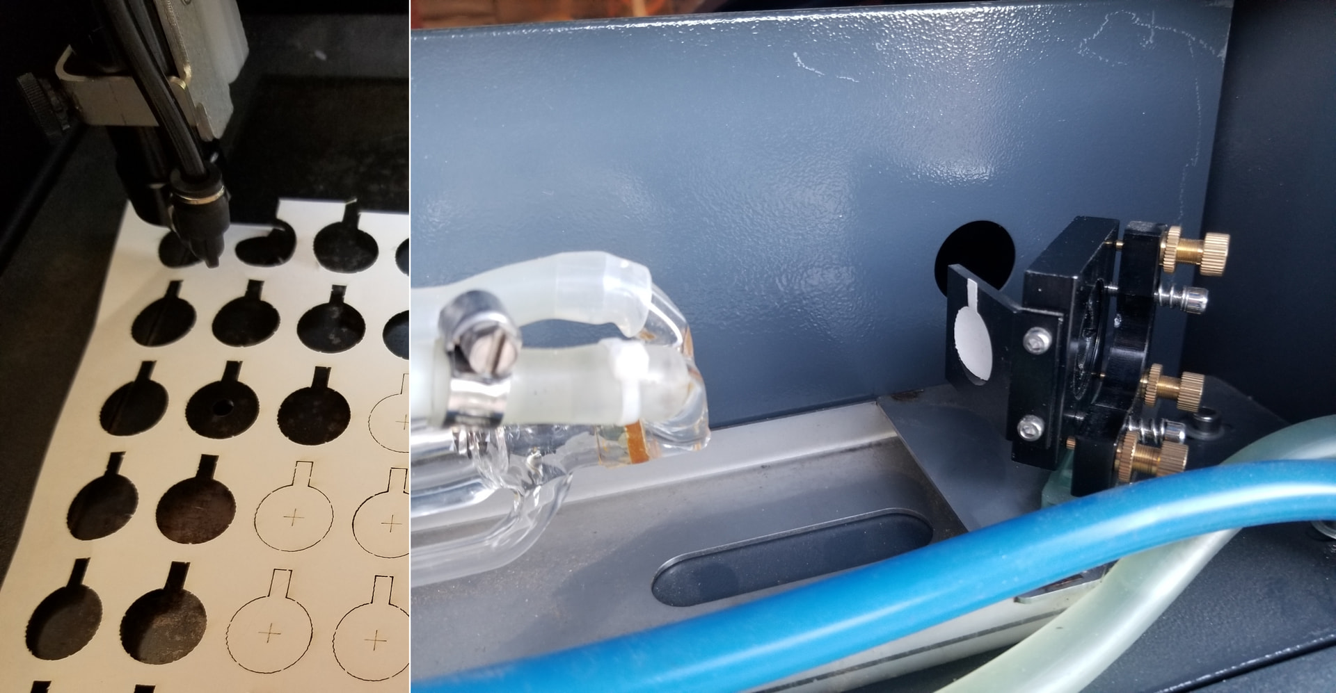
Hi, I recently bought an aged CO2 laser which came with virtually no info (a story for another day). In a box of gubbins came these, below. I’m guessing that these are simply something to tape in front of the mirrors when calibrating the focus, though I then don’t understand why there would be three of them. Has anyone seen these before and can explain how they are supposed to be used?
If that were the case, they’d have an assortment of nasty burn scars.
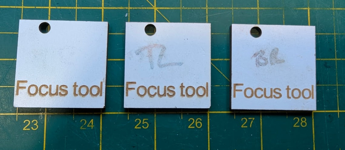
The “Focus tool” labels suggest they’re intended to slide under the nozzle to set the proper distance to the material. Depending on the focus distance, they may be used either laying flat or on standing on an edge.
If all three are the same thickness / width / height, then you have two spares.
If they’re different, then they’ll correspond to the slight defocusing needed for special effects on materials you don’t have.
Stacking two half-inch thick slabs would be the additional distance needed when you change from a 2 inch lens to a 3 inch lens.
Other than that, it’s a mystery!
Yes, I thought the same, and clearly they don’t have any scars, which is why I thought maybe the idea was to put tape across the front. Seems a lot of hassle though, when you can just use a bit of paper.
I don’t think they are thickness gauges, they are all identical and there are no scuff marks on the faces or edges. Although it doesn’t show well in the photos, they have ‘TR’, ‘TL’ and ‘BR’ written on them in black marker (one set of letters per square). I’m guessing these stand for Top Right, Top Left, Bottom Right. Actually, even as I write I’m having an idea, that you place these flat in their respective positions on the honeycomb, to be able to see the red dot. In other words, a previous owner was using the red dot as the means of calibrating the mirrors, rather than the laser itself. Though why you’d write on them is still a mystery.
Maybe they’re blocks to level the platform after a mishap or some nasty servicing.
With the drive belt loosened, you’d twist three of the four leadscrews to put the platform the same distance under the nozzle at those three locations, so the focus would be correct all across the platform.
Stipulated: still guessing. ![]()
Ahh, yes, that would make sense. I haven’t checked the bed level yet, probably a good place to start.
You don’t say what kind of machine you bought or got. I won’t speculate about the plastic parts and will rather start making a focus gauge myself and check the whole machine.
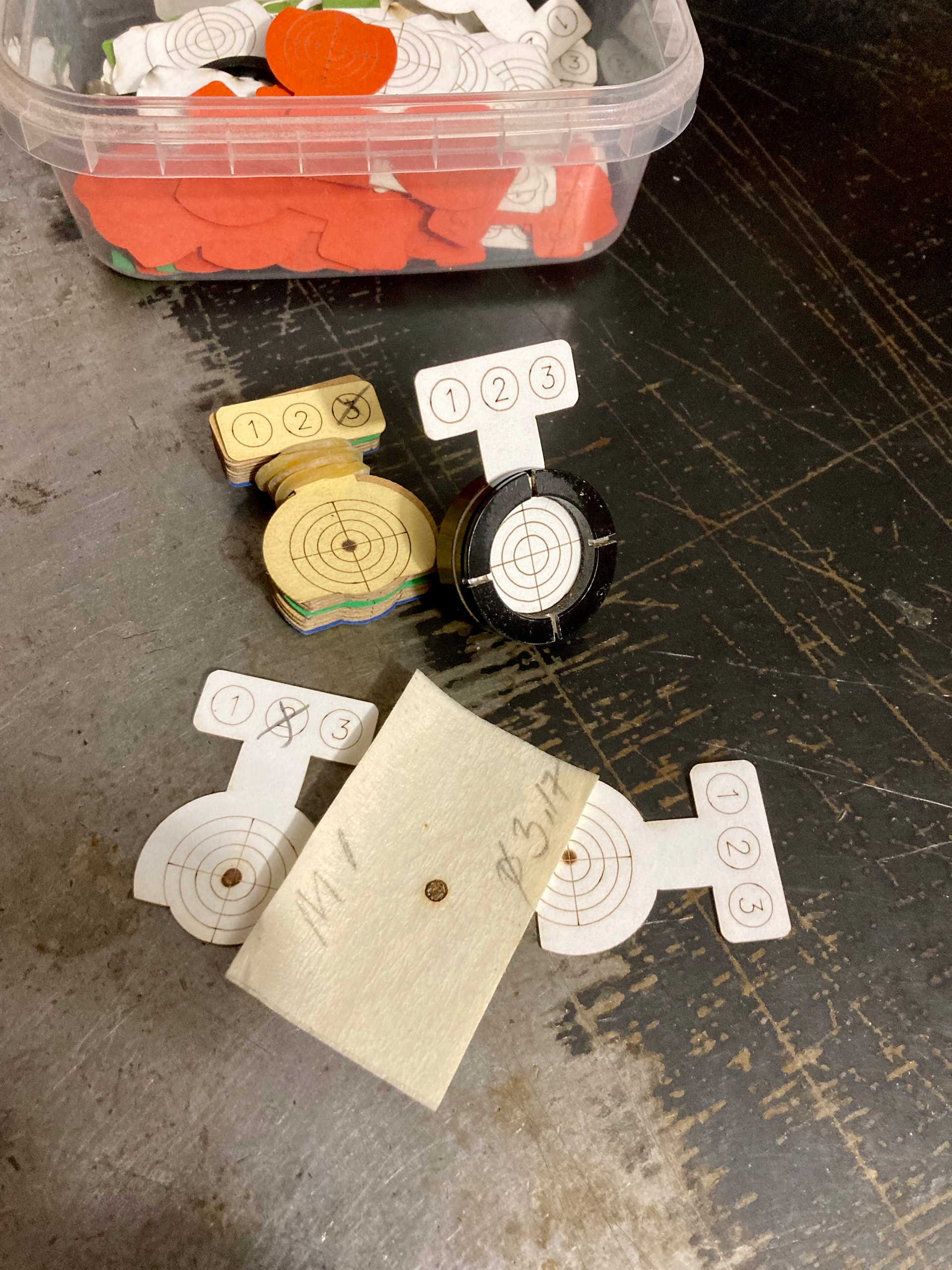
For mirror calibration I also use something completely different than what you show, but in the beginning, to get the machine running, masking tape is fine. Later you can find a target holder and make your own targets, it’s much more precise than just tap.
Hi, could you share details, or signpost me please? I have the machine running and am now setting about optimising it’s performance, so the more accurate the better.
I didn’t name the machine because, ironically, it can’t run Lightburn (yet) and I didn’t want to distract from my question. However, the machine is a HPC LaserScript, labelled as a ‘Mini 500’. HPC had never heard of this machine but have been very helpful anyway. It was sold as a LS6040, but it’s not, leastways the working area is about 58x40 max. (I probably should have insisted on a return once I discovered this, since it was also sold as in good working order, which it certainly wasn’t. But I didn’t so that is now moot). The ID plate on the rear is faded to the point that I cannot get any useful info from it. Essentially, it is an old - probably 15 - 20 years old - solid, LaserScript with a LS2400 controller, which can apparently only run an app called LaserCutEngrave. I cannot overstate how much I miss Lightburn but that’s probably also for another day.
Thanks for the explanation. At least it is a solid base of a laser machine, if I have understood it correctly, so you have the possibility to restore/upgrade the machine.
The calibration tool I mentioned is this one.
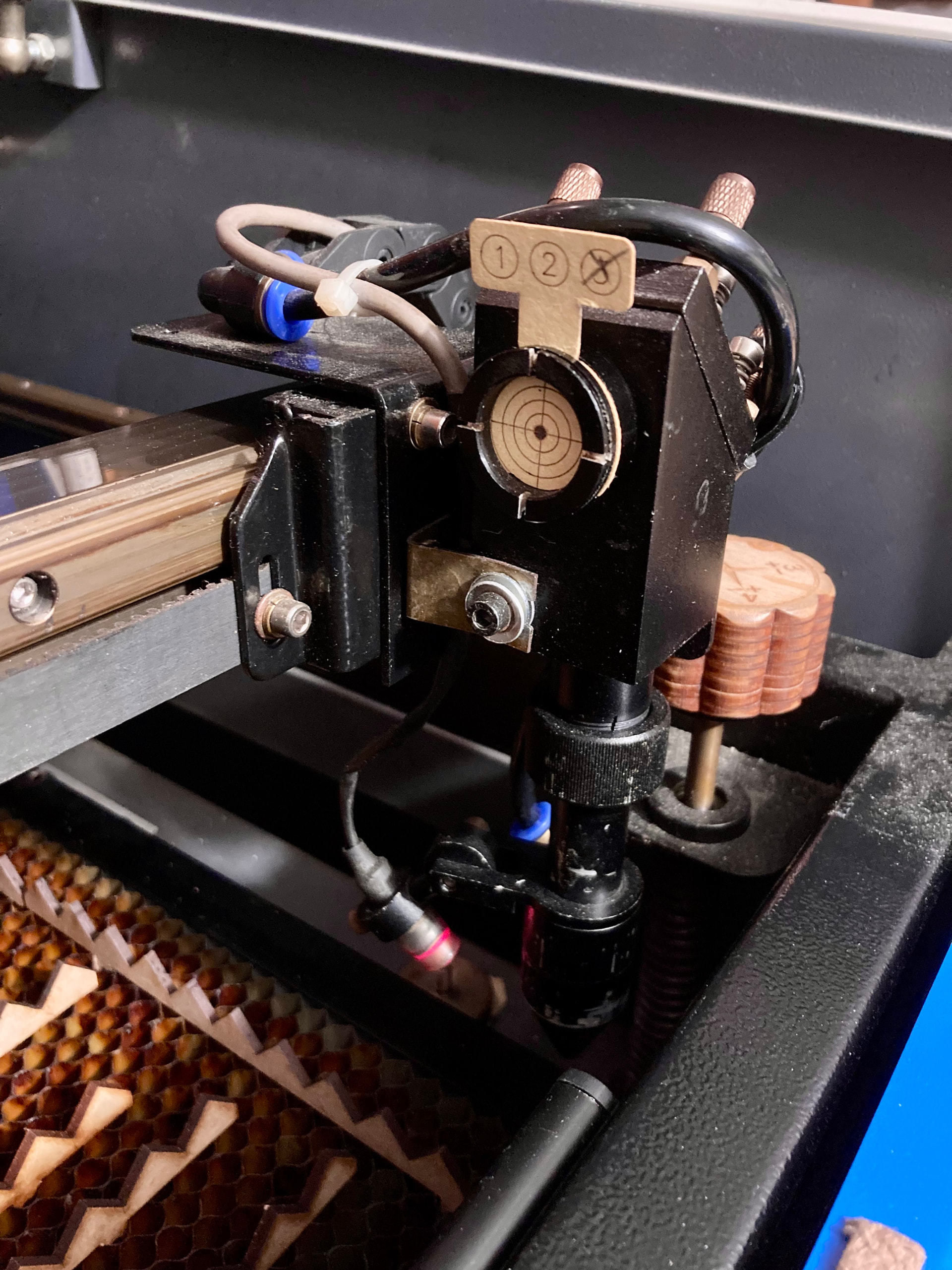
(I have however removed the copper cross on one tool, and changed it so that I also have the opportunity to insert my targets on the Z axis)
If you want my target file, please tell me
Possibly you have a completely different mirror holder system like most Chinese machines, in this case it needs to be adapted.
That looks like a good idea. I’m not sure the Cloudray kit would fit my mirror holders but I like the idea of targets and I should be able to easily make holders using a 3D printer.
Yes, I think it is fundamentally sound and solid. I don’t know if it would be cost effective and practical to upgrade but if it is, I can see myself looking at this a little down the line.
1 Like