Hi!
Im really struggling. I have co2 laser 60w 60 by 40
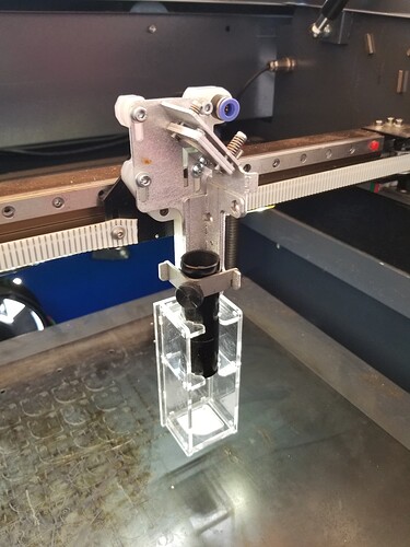
The first and second mirror are aligned but 3rd mirror is having issue and when im firing the beam is hitting the nozzle not the bed. What can possible’s be worng!
You have a problem with your alignment…
If M1 and M2 are OK as you write and you do not hit M3, M2 should be set to “catch” M3 correctly. Another problem may also be your nozzle which may not be perpenticular.
Want to show us a picture with the results of M1, M2 and M3?, It makes it easy to help.
From your wording, it worked at some point, so it must have been aligned properly then… that would lead me to think you messed up the alignment to cause this… ?
I’d word it differently… M1 and M2 are ok, you need to catch the beam with m3. With limited ability to adjust M2 → M3, you have to move M3 to where the beam is going.
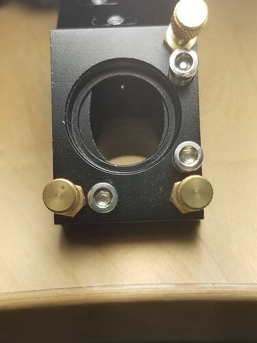
This can be difficult, especially lacking the adjustments on the head/mount.
Ensure your head is correctly aligned… mine has the mirror offset within the head.
Follow @bernd.dk lead and post us some photos…
Good luck
![]()
thank you so much for you help.
so
M2- M3 the beam is going downward direction M2 mount is perpendicular. its is possibly the head as well as the nozzle as after 1000s of adjustments I managed to align M2 and 3 but the beam is not perpendicular.
Also I took the mirror off and placed a tape over it. and the beam is not hitting the centre. I tried everything its all in 90 degree angle.
thank you for your time
so
M2- M3 the beam is going downward direction M2 mount is perpendicular. its is possibly the head as well as the nozzle as after 1000s of adjustments I managed to align M2 and 3 but the beam is not perpendicular.
Also I took the mirror off and placed a tape over it. and the beam is not hitting the centre. I tried everything its all in 90 degree angle.
I also realised that the the beam in laser tube is hitting the metal neck of the glass casing.
https://youtube.com/shorts/3dFem223njQ?si=U8Zwnb8RGZbtjLab.
thank you ![]()
It is often seen but has no (to my knowledge) negative effect.
ok. thank you
In order to refresh my own ability to set the laser beam and for reguert maintenance of the machine, I have loosened all the screws on all mirrors and the nozzle holder as well. (Positioning of the CO2 tub itself I have not touched)
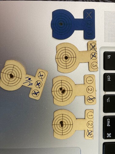
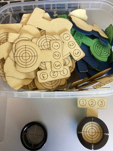
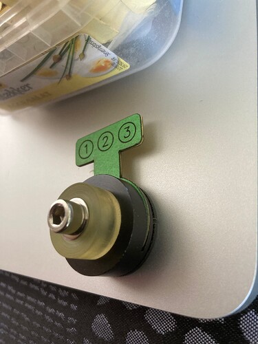
At Cloudray (CO2 Laser Head Set – Cloudray Laser) I bought the target holder that I am happy with. They are a little modified, the copper wire in the center did not give me the precise picture of the beam I want. I have made the target discs myself in lightburn ![]() and produced by 270 g/m2 paper. It’s reasonably heavy and burns not right away.
and produced by 270 g/m2 paper. It’s reasonably heavy and burns not right away.
The art of adjusting the mirrors is not to hit just center, it is achieved fast for M1, but to hit M2 closest and farthest away from M1 and then M3 with M2, also in both outer positions. For these 2 mirrors I used about 40 target discs (usable on both sides)
It takes patience and fine feeling in the fingers to fine -tune the mirrors. But once you have found the trick and instant sees the result of fine tuning from the screws on the target disc, the mood rises.
I always try not to touch more than one mirror at a time, and one direction at a time. I also avoid going back, if M1 and M2 are ok then it’s ok.
To determine perpenticularity, I burn an impulse with the nozzle 2-3 mm from a piece of wood, defocuses at least 50 mm, without moving the tree with the first shot!, And then I shoot again. It works for me better as this method where you use tape directly on the nozzle. If both shots are hit in the center you are ready to produce with the machine again.
Try, not to go to comromisses with the results, that’s also why I not just use tape and then have to guess whether it is in the center or not.
In some cases where the tube is not placed correctly or if the whole frame is skewed or/and not 90 degrees angle to each other … it requires a completely different procedure.
Centertargets.lbrn2 (1.3 MB)
ouch
I never go backwards… if you have to do that, it must not have been aligned in the first place.
When I change something, I rarely do it from scratch, but in the the worst case, I set my mirror screws to the middle of their travel.
I also use a piece of wood or something to ensure I’m hitting m2 at maximum distance.
Once I’m on the mirror target, pulse it at minimum distance for a target, then move to maximum distance.
At maximum, I have fingers on the mirror adjustment and the pulse button (quite a stretch). I can pulse it, move the mirror and pulse it and do that until the two line up…
Only then do I change targets and make a close distance mark and check it with maximum distance.
If you’re hitting m2 at all, the most m2 at close distance can be off, on my machine is around a mm, certainly less than 2mm.
The ovals are the mirror, as seen from the beams view, based on them being 45 deg, a 20mm mirror is 20mm vertically, but across it’s other axes it only about 14.1mm – with m3, it’s the reverse. If I rotated them as we normally see them, the lines I’m trying to show, would end up on top of each other.
The bottom line between m1 and m2 at it’s furthest points, is the beam perfectly hitting m2, both near and far. The top line is the center of the beam to edge of mirror.
Closest to m1, m2 is a 160mm and it’s 340mm at it’s furthest point.
This only demonstrates how limited the spot on m2 can actually move at it’s closest distance. These lines are infinitely thin, a real beam is at least 5mm, subtracting 2.5mm from the edge of the mirror.
This is why I use the described procedure, it’s relatively easy and fast to get them aligned if you’re on the target in the first place.
Going m2 → m3 is initially the same, but how it’s adjusted is a bit different on mine. I have targets that fit on the face of the mirror, on the top of the down tube and further down to a simple jig for the final target.
It’s very critical that the beam go down the center… if it doesn’t it will come out at an angle, so your cut will have a vertical angle associated with it.
I was advised and find it true, that m3 needs to catch the beam and it needs to go down the center of the tube. The lens is what makes the makes the machine work, so take care with the input to the lens…
If the beam needs to move in the X direction across the down tube, then you must move m3 in the Z direction. If you need to move it in the Y direction m2 must be able to be moved in the Y direction.
There is an instance where going back to m1 works… if you have the odd corner not working. This is more than a sensitive adjustment. It can easily ruin your whole alignment if great care for a minor adjustment isn’t used.
Sorry to ramble, hope I didn’t miss anything… Sing out if you have problems with any of the above.
Good luck
![]()
This topic was automatically closed 30 days after the last reply. New replies are no longer allowed.
