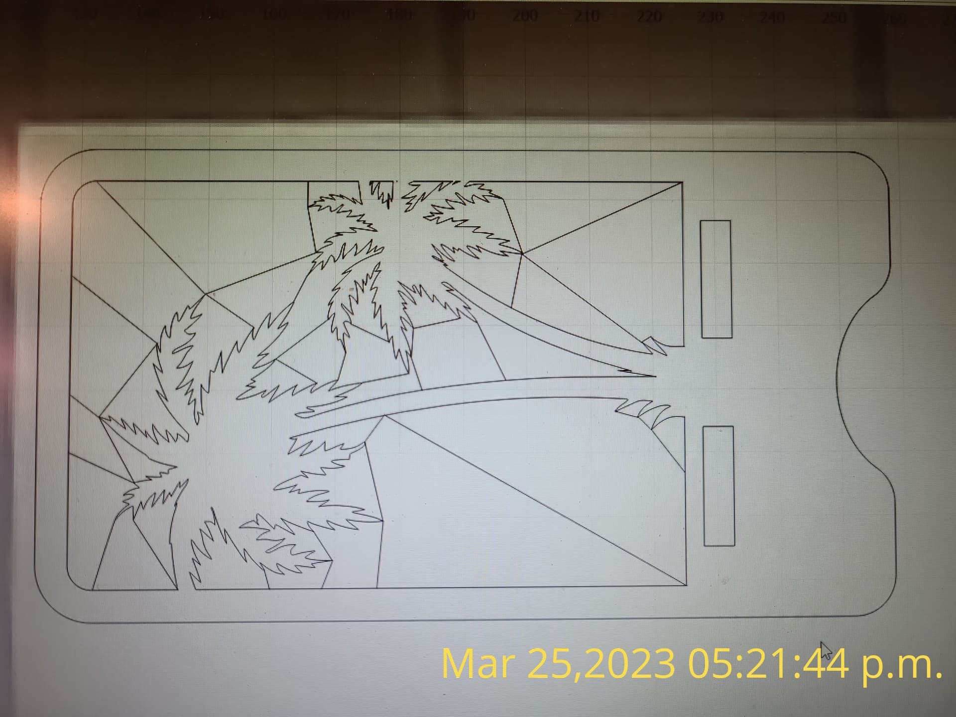
I have been reading alot of other posts on this forum and trying to adjust my settings as per what others have suggested but as of yet I have had no luck. Right now I am currently on my 52nd test and still can’t figure this out. What’s happening is the laser does not engrave the image on the screen completely. It’s almost there but it seems like its always off by a couple of mm, which will basically mess up all my future designs. I’m just going around in circles trying to figure this out. Please see photos to understand, as you can see some of the lines either don’t extend up all the way or are shifted over and do not connect. But on the screen they all do. Usually all the other tests are alot worst!
Mechanically I have checked all tightness of belts, they are very good. Not super tight and not slagging, I have cleaned all my rails and wheels. I truly believe that its not a mechanical issues due to the fact that when I do change different settings on the external stepper drivers and modify the config file I can literally see small changes. The only problem is I have yet to fully lock down a setting to help my situation. I am probably out to lunch when I say this but it seems like basically the only settings that people are modifying to fix a situation similar to mine is the seek rate, feed rate and acceleration. I have already configured my laser cutter to the right steps as per alpha and beta steps per mm on lines 15-16, the laser is cutting a square 100mm x 100mm, which is drawn on the screen. With the exception of any amps above 1.5 on my external stepper drivers I have literally tried each microstep starting from 32 down to 4 using 1.5amp down to 0.5 for each one. Currently my best results were with the 1/4 steps at 0.5 amps, which doesn’t seem right. You would think that at the very least I would be able to use 1/8 at 1 amp and get great results but NOPE. Is there any other settings that people have been adjusting in the config file to get their best results that I haven’t touched on? Or is it just going to be a situation where I will have to do like 400 tests? I am using nema 17 stepper motors with a cohesion3d board with external stepper drivers. It always homes itself when I ask it to so no problems on that end and I have attached my config file if someone would like to review my messed up settings.
I know you’re confident that this isn’t mechanical but this type of thing is almost always mechanical or electro-mechanical. If the alternative is bad g-code I’m confident the chances of that are quite low. I’ve never seen LightBurn generate wrong g-code geometry.
Can I suggest you run a few tests? That may help narrow in on root cause.
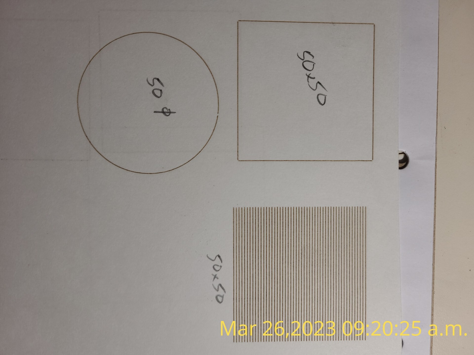
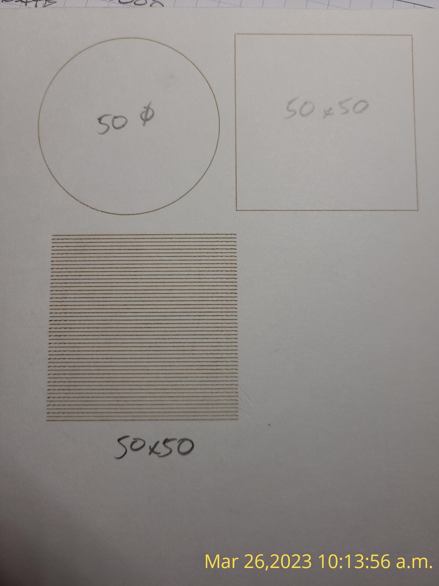
Create a 50x50 mm rectangle and burn the outline
Create a 50x50 mm circle and burn the outline
Create a 50x50 mm filled rectangle, set interval to 1 mm
Hello,
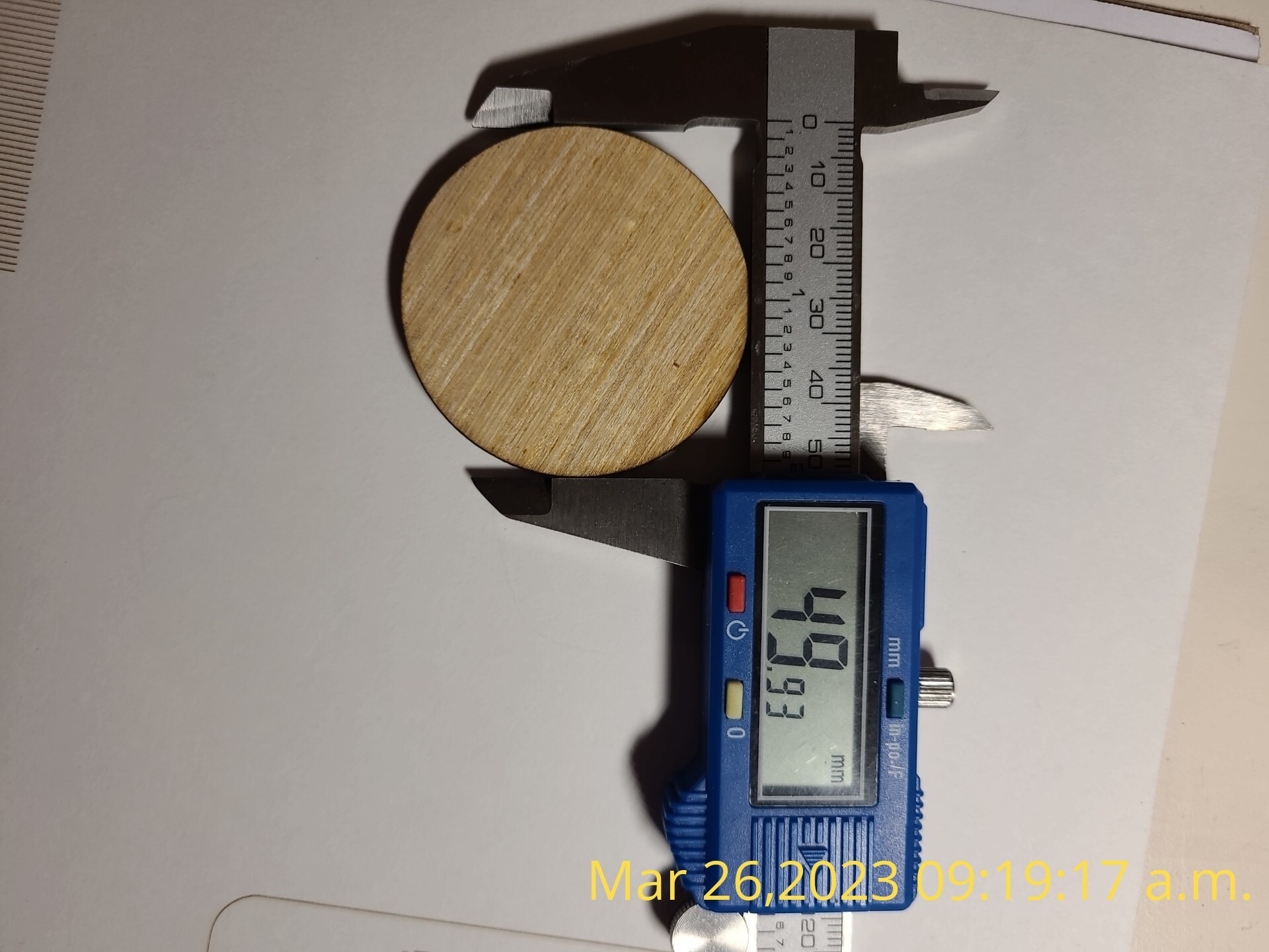
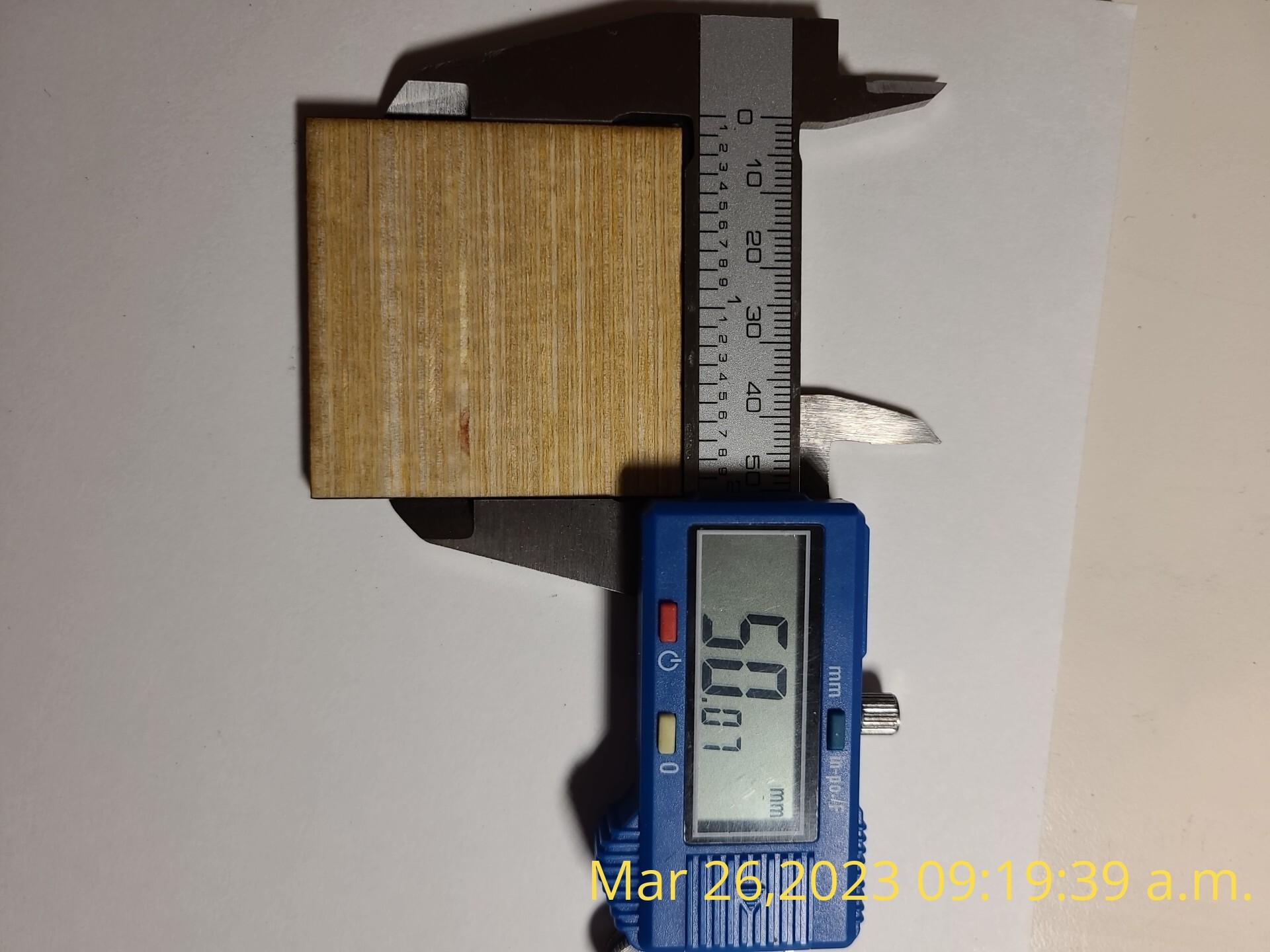
Please see attached photos of my results. I have included a photo of all the shapes engraved into cardstock, both shapes cut out of wood showing the results from the caliper and another one of my test’s using the same settings.
The gaps in the circle and square show there’s at least a millimeter of mechanical backlash in the Y axis.
Your profile says “Home made laser”, so I don’t know how the machinery moves, but the backlash can be anything from a loose setscrew on a pulley to mechanical flexing due to aggressive acceleration and speed.
Also, if the laser has an unusually large platform, on the order of a meter square, then it may be working at its mechanical limit of accuracy. We had a long go-round involving tiny errors on a huge laser that turned out to be mechanical flexure:
The later comments from folks with hulking lasers gives an indication of the problem areas.
If you’re using NEMA 17 steppers, set them for 1.5 A and do not change it again. They should run on the comfortable side of too hot to touch.
If they’re direct-driving a GT2 belt, then set them for 16 or 32 microsteps, set the step/mm accordingly, and do not change it again. The config file has 40 step/mm = 0.025 mm/step, which is somewhat coarse but will work fine.
This may be a laser power-vs-speed issue, where the controller reduces the power at low speeds and the power drops below what’s need to mark the material. I don’t know how Smoothieware makes those calculations, but similar problems have cropped up with both GRBL and Ruida controllers.
The problem seems to happen in edge cases where the minimum power or speed (or both) dropped too low. Tweaking the settings away from the edge may require a few experiments, but ought to be straightforward once you figure out where to look.
Hello Ed,
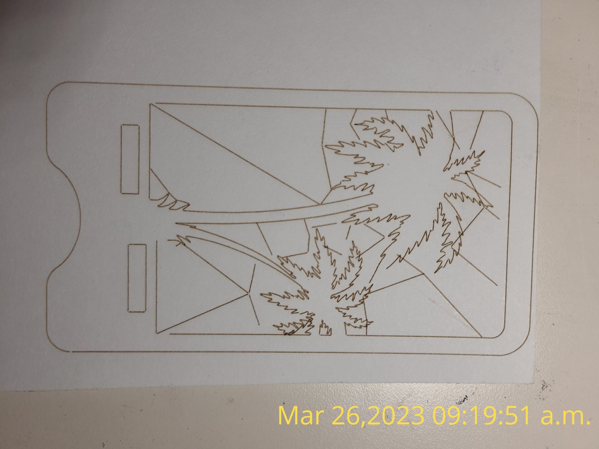
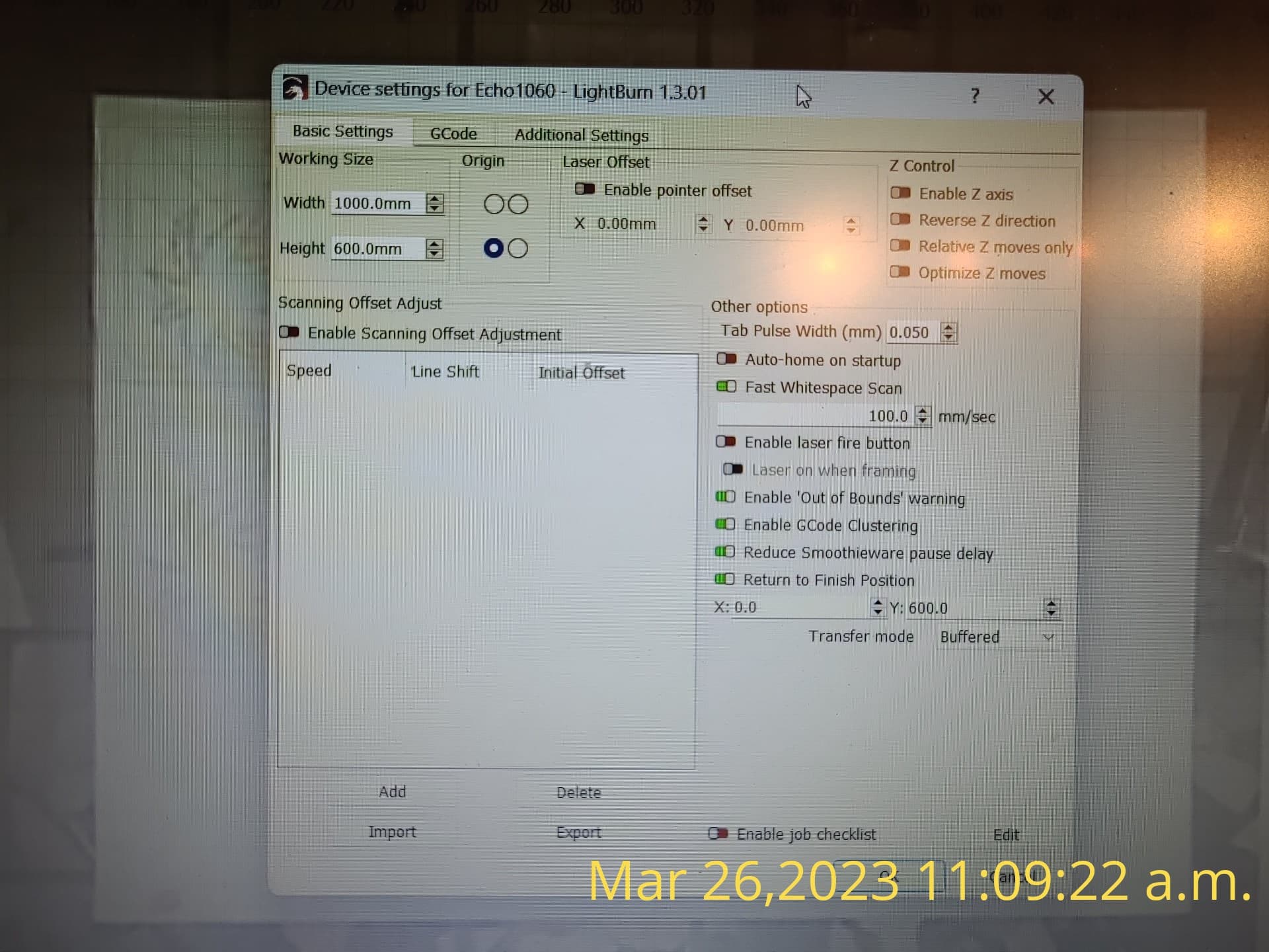
Thanks for the reply, this morning I increased the acceleration to get rid of those gaps as you can see in the photo attached. Its now at 2500mm per sec. Some lines are a bit wobbly so maybe a bit lower setting will work for closing the gaps. Yes my homemade laser is bigger but not huge compared to others I have read on the forum, the bed is 1000x600. I will check again all screws,bolts,belts,rails and such. Yes I know I’m comparing apples to oranges when I say this but I started off with an M2 nano in my machine it worked fine. I thought that something might of happened to the rails going out of square and such but I never touched them during my conversion over to the cohesion3d board. But like I said earlier I will check all mechanical point again and also check to see if my gantry is square.
Agree with @ednisley on the backlash although I think this may be on the X-axis assuming the photos are all rotated 90 degrees clockwise from how they were burned.
I suspect there’s something else going on to account for the palm tree design. What are the dimensions for that design? Trying to get a sense of scale.
The bidirectional scan test has alternating wavy ends. I assume the wave ends represent the start of each burn. Typically this is caused by instability in the laser head assembly or a loose lens. Might want to review there as well.
I’m curious how increasing the acceleration would have resolved the issue. Normally higher acceleration would exaggerate those issues.
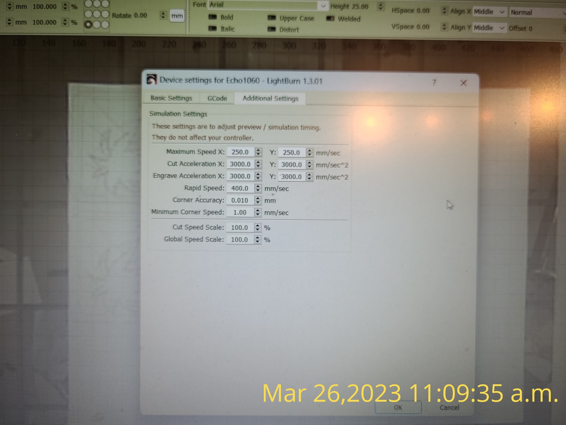
Separately, can you take a screenshot of Edit->Device Settings?
Attached see photo’s of my lightburn settings. Also I don’t really know what to tell you regarding the increase in acceleration fixing one of my issues, it just did LOL. I did notice that the slower the acceleration was it had less wobbly lines…but then bigger gaps at the ends of my connecting lines…for that specific issue its like I’m damned if I do and damned if I don’t.
I know this might sound really stupid but has anyone with a larger machine just used the drivers straight from the board?..instead of using an external stepper driver. Would that even do anything to help my situation?
I think the higher acceleration (and corresponding deceleration) causes mechanical overshoot, which hides the mechanical backlash. Lower acceleration removes much of the overshoot and reveals the backlash.
Which implies the gaps are on the order of a millimeter, around 0.1% of the maximum travel. Improving that will require careful attention to detail starting from first principles.
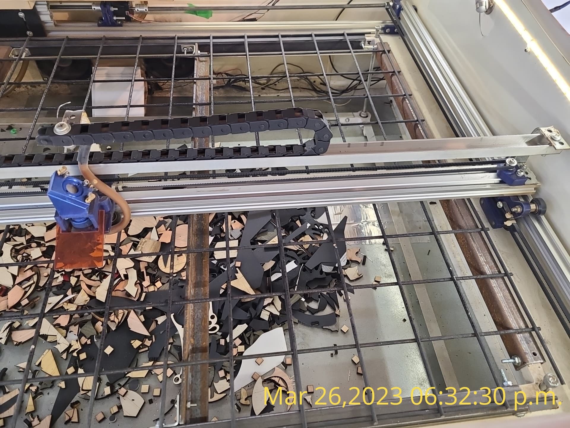
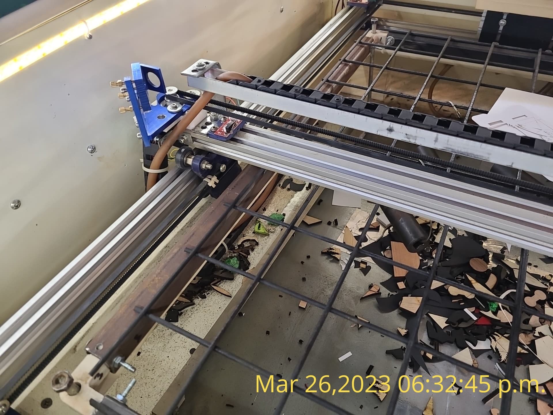
What does this machine look like? In particular, what are the rails / guides along both axes? If the hardware resembles a typical diode laser, the speeds and accelerations are extremely high.
However, I see some rocks in the path to sub-millimeter precision in a machine of that size:
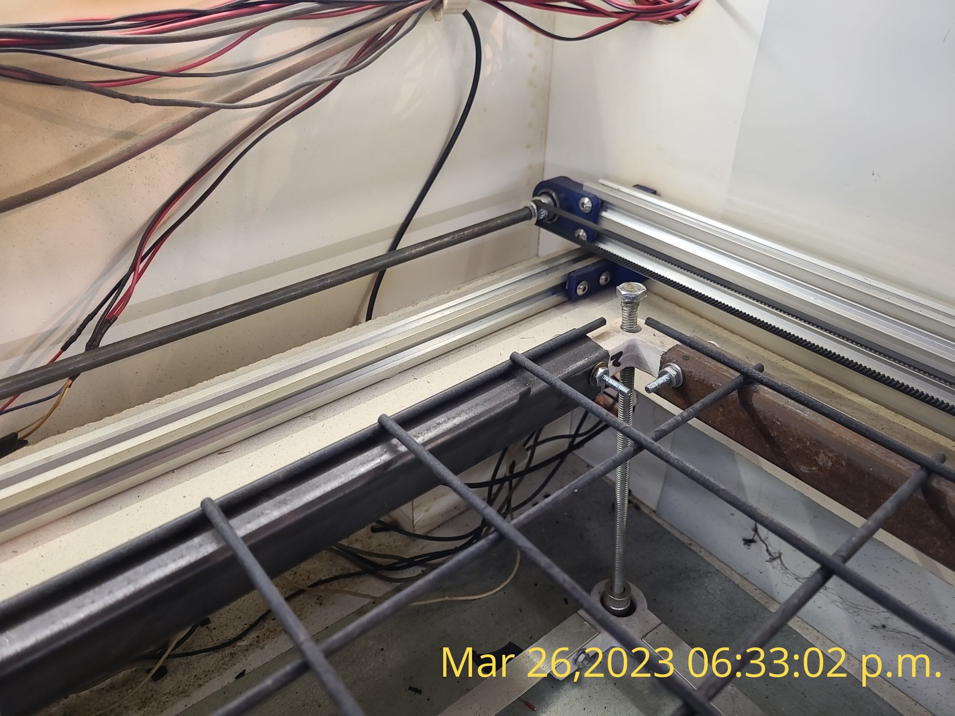
The belly where the belts wrap around the end pins, secured with zip ties, will flex
There’s no way to get all the slack out of those loooong GT5 (?) belts
If those are 3D printed fittings (*) under the gantry, they’re not stiff enough for the weight they’re carrying
Plenty of cantilevered mass on the gantry
Silent-but-flexy rollers
None of those are criticisms of a very functional machine (the chip tray tells the tale!), just places where mechanical flex will happen without anything being obviously wrong. Stack up enough flex and it becomes noticeable in small objects with tight tolerances.
For fine work, the machine will require less aggressive acceleration than for “normal size” cutting, simply to keep the flex under control.
Some changes, roughly in decreasing order:
Wrap the belt with teeth outward around the end pins / screws
Cinch the belt ends at the pin with no belly
Add a support roller under the long belt spans to reduce the droop & flex; this may allow slightly more tension.
Swap those gnarly steel brackets on the gantry for aluminum: every gram up high counts against stability.
Likewise, swap in plastic for the aluminum U-channel along the gantry
Aluminum brackets instead of 3D printed parts
Tweaking the belt ends might make an obvious / immediate / Oh wow! change, but the rest probably aren’t practical / cost effective.
Set the acceleration low enough that you can watch the axes winding up on long runs, then compare some test pieces with progressively higher accelerations. Somewhere in there should be a set of X & Y values hard enough to be practical and soft enough to minimize the flex.
(*) If those are waterjet-cut aluminum: I grovel, I abase myself, I kiss your feet, I beg your forgiveness.
Hello Ed,
Thank you for the suggestions, I do like the idea of rotating the belts so that its a smoother ride. Also getting rid of the belly at the end of the belts is a good thing, I could definatley make those tighter up against the bolts holding them. Adding some type of bracket / rail / wheel system under the belts will take some thinking about fabrication in order to stop any potential slack in the long belts. That’s funny about your comment regarding my gnarly brackets!..you are not the first person to say that. I will eventually get around to replacing them, its just what I had laying around in the garage at the time of construction and it worked. I did look into replacing most of my plastic parts by getting a guy in town to machine me off a few pieces in metal…just I gotta sell a few more crafts to buy them. My way of thinking is that my machine should almost be self sufficient. It’s not the prettiest by a long shot but up until 2 months ago it was functioning very well for home built, until my upgrades…lol…I know I will figure out all my little problems by trial and error and also by the help of everyone on this forum and when I do I’ll be golden!