Good day guys please can any one assist. We have built a frame for a laser based on our own dimensions and using a controller of choice in this case a MKS DLC v1,1. The problem that we have run into is that the frame is suppose to be 1100mm by 1400mm but when we put this into the Lightburn software the machine does not move as expected much less then it is suppose to and it continuously fails its homing cycle, however when we moved the machine manually and used the values accordingly as seen in the parameters the machine works perfect.
Do move controls in Move window work as expected? Up goes up, down goes down, etc?
Do jogging distances correlate to the distance specified in Move window? Disable continuous jog in order to change distance value
Confirm that your machine has homing switches
Homing cycle is independent of LightBurn. Does the machine attempt to home when first powered on? If so, describe the sequence of events after power on.
Can you elaborate what you mean by this? How are you moving the machine? Where are the values/parameters that you’re referring to?
Please provide the following:
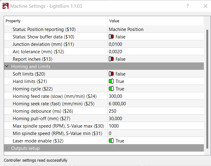
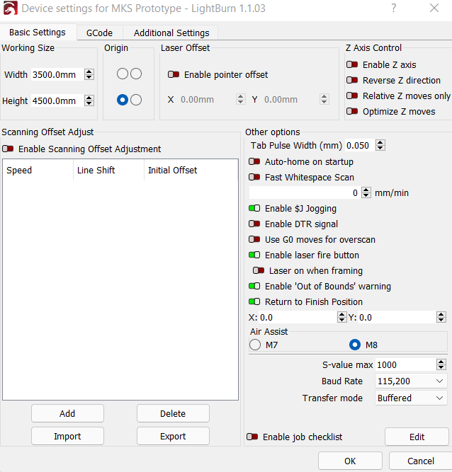
Screenshot of Device Settings
Screenshot of Settings
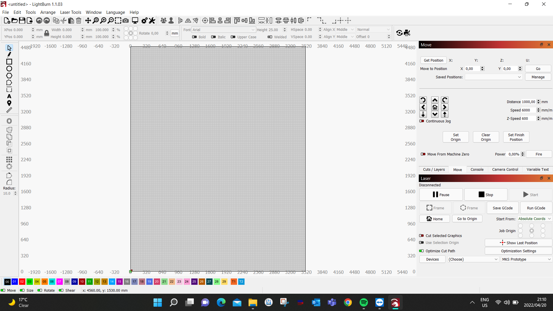
Full screenshot of LightBurn with Move window and Laser window showing.
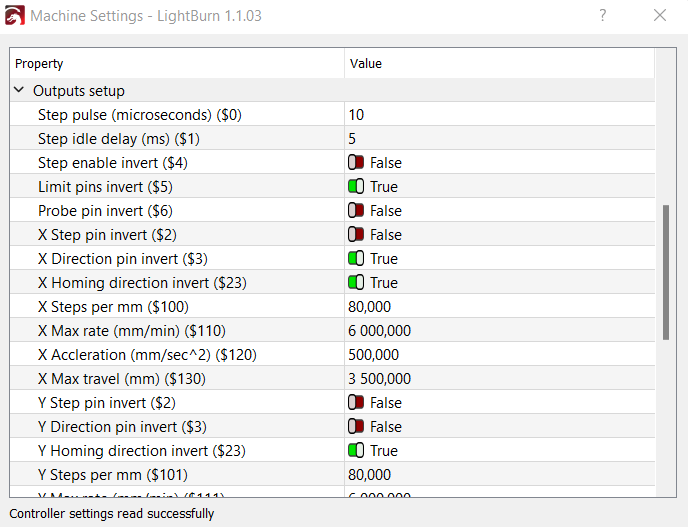
You say that the work area is 1100mmX1400mm but i see in you parameters $130=3500 (X axis) and $131=4500 (Y axis). Where and when you set 1100 for X and 1400 for Y?
Does the homing cycle fail immediately, or after moving some, then it fails?
Things to check…
If the homing cycle fails immediately then the limit switches are most likely connected or configured wrong. (NO instead of NC, or visa-versa) check $5
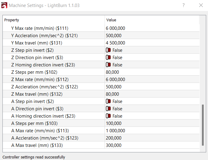
If the homing cycle fails after moving a bit, then the machine max size doesn’t match the steps/mm according to your axes drive mechanics. First check if you tell Lightburn to move an axis 10mm, that it moves 10mm. If not, recalculate for your steps/mm ($100, $101, $102). This would be because the homing cycle moves 150% of the axes max travel ($130, $131, $132) during homing, or until it contacts a limit switch. If the steps/mm is set incorrectly for you drive calculations, then the controller might think the machine has moved farther then it actually has. You will need to make you steps/mm calculations based on the drive type (lead screw, belt and pulley, etc) along with the microstepping setting on your drivers (1/2, 1/4, 1/8, 1/16, 1/32, etc) and the full steps per revolution of you stepper motors.
The setting of 80, generally corresponds to a belt and pulley drive system, with 20 tooth pulleys, 2mm pitch, and 1/16 microstepping, with 1.8 degree/step, 200 steps/rev motors). If yours is different, like different sized pulleys, different microstepping, different belt pitch, .9 degree motors, etc, 80 won’t be correct. Now, this is just an example. 80 could correspond to different settings, but it would be very specific.
If your axes are driven with lead screws, those usually have a much higher steps/mm number because of how it transmits linear motion. With the above microstepping and steps/rev stated above, your steps/mm would be 400 when using a 8mm (2mmx4start) pitch screw instead of 80, and that’s a pretty steep pitch for a lead screw.
Here’s a link to a nice calculator for motion control.
Even though you max travel is set way larger than your actual working size, if the steps/mm is drastically wrong, it will still fail the homing cycle.