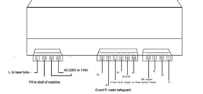
I don’t have a clue as to pinout of these devices, but looking them up…
The wiring should work this way… grbl controllers do not have the same control interface as most of the commercial dsp type controllers.
The potentiometer (pot) controls the dc voltage on the IN terminals of the lps which controls current through the tube… The higher the voltage (5V or less) the higher allowed current.
The PWM goes to L which is laser enable.
This type of interface sets the tubes current by the pot and turns the tube on and off at the specified period.
If you set it for 50% pwm, the tube runs at 100% (or whatever the pot is set) when it turns on, then it’s turned on 50% of the time and turned off the other half of the period.
All the lps I’ve been exposed to have a performance specification of 90% voltage <= 1mS.
This means anything over a 1kHz pwm will drive the laser enable faster than the lps can respond, if it’s within specifications.
I think 5kHz is 5 times quicker than it can possibly respond…
Make sense?
![]()
