Hello! I have an MKS DLC32 V2.1 board. I need to mirror the Y-axis to the Z-axis driver.
On the stock firmware (v2.2), when I send the command $450=1, I get error:3. I also tried FluidNC, but I can’t get it to work correctly with my screen.
Can you please help me with a working firmware or configuration to enable Dual Y motors?
My current settings ($$): $123=200.000, $124=200.000, $125=200.000 $130=450.000, $131=450.000, $132=50.000 $133=300.000, $134=300.000, $135=300.000
Based only on the details you provide, I can’t quite understand what you want or the need to mirror the X-axis on the Z-axis.
The board has slots for 3 distinct axis drivers and one output for each, except for the X-axis which has two (I don’t remember if they are in parallel or inverted).
Having no knowledge of FluidNC, I can’t offer much more guidance other than to ask:
Wouldn’t changing cables solve the problem?
What parameter is that?
Perhaps if you provide more detailed information about your needs, we can help you more effectively.
There are also people here who prefer to use FluidNC and are more familiar with the firmware than I am.
Sorry for the confusion in the title. I have a large laser machine with two stepper motors on the Y-axis.
My MKS DLC32 V2.1 board has X, Y, and Z driver slots. I want to use the Z-driver slot for the second Y-motor (Dual Y).
About $450=1: I found this command in some MKS DLC32 manuals for “Mirroring Y to Z”, but my board returns error:3.
I cannot just use a splitter cable because I want to be able to auto-square the gantry later. That’s why I need a firmware that supports “Dual Y” or “Z-mirroring” for this specific board.
Does the stock firmware (v2.10/v2.2) actually support $450, or do I strictly need FluidNC / grblHAL for this?
My laser machine also, but it’s not a large one so I assume you need more powerful stepper motors.
Based on my knowledge, I can’t help you with that.
I’ve never heard of this, but I’m no expert on the subject either.
Personally, I understand the concept and even its usefulness, but I think it’s a bad idea.
In my opinion (it’s just an opinion), any problem that arises on that axis (X) will always create doubts as to whether it’s a problem with drivers, wiring, motors, dirt, etc…
A driver supplying power in precisely the same way to two motors eliminates half the doubts.
I would opt to increase the driver’s power if possible and power both motors with the same driver through each of the ports dedicated to the X axis. Sometimes keeping it simple helps.
But I could also be wrong, either because I don’t quite realize the dimensions or because I’m seeing things differently.
As I mentioned before, I’m completely unfamiliar with it.
I would do a search on Gitub or wait for opinions from someone familiar with FluidNC.
All I can do is wish you good luck, because the subject has piqued my curiosity and I will continue to follow the topic.
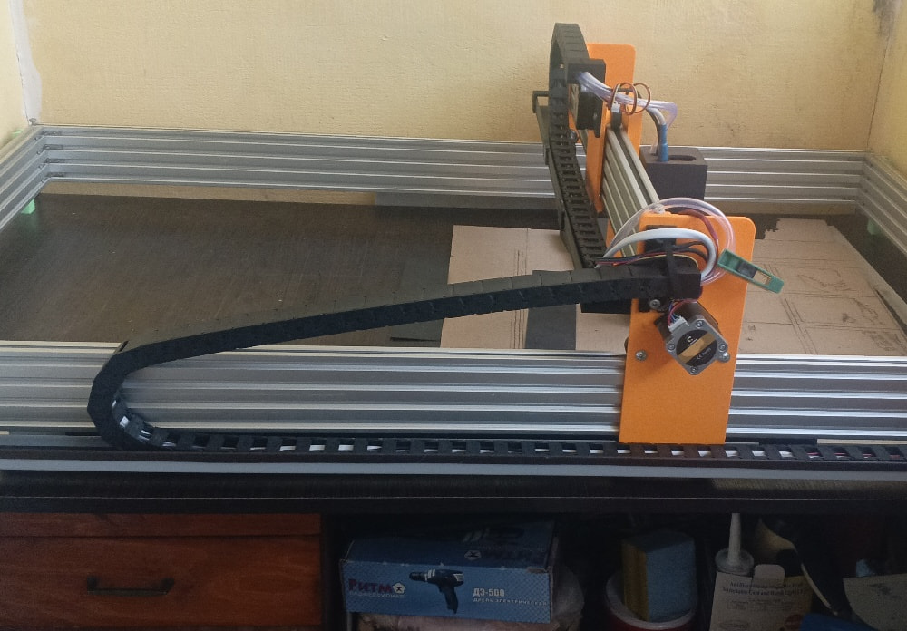
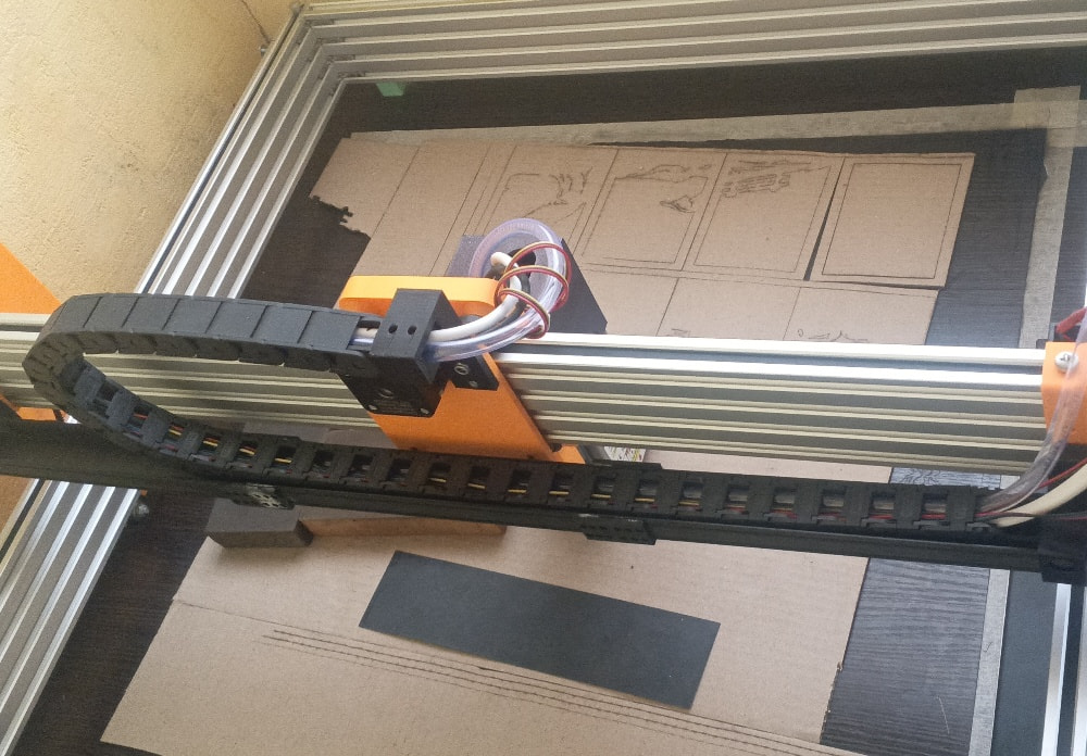
Hi Kuth, thank you for the feedback. Here are the photos of my machine.
As you can see, it is a custom build with a large and heavy gantry. I am using an MKS DLC32 V2.1 board, and I have all 4 driver slots populated (X, Y1, Y2, and Z as the second Y axis).
Using a single driver for both motors on such a wide gantry often leads to racking (mechanical tilt) if one side skips a step. That is why I need “Auto-Squaring” via FluidNC to ensure the gantry stays perfectly perpendicular.
I would be very grateful if you or anyone else familiar with FluidNC could help me with a config template for this board to run Dual Y on the Z-driver pins.
“The main reason I want separate drivers for the Y-axis is to achieve Auto-Squaring. On a gantry this wide, manual alignment is difficult, and FluidNC’s ability to square the axes during homing is exactly what I need for precision.”
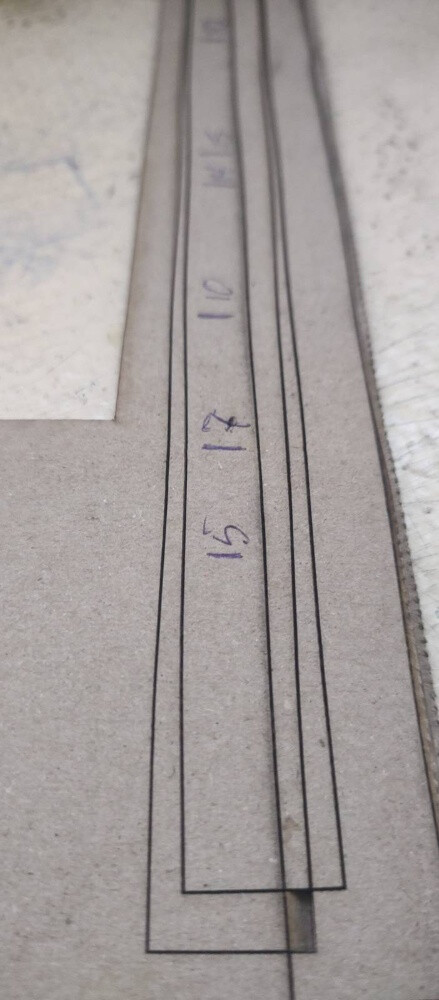
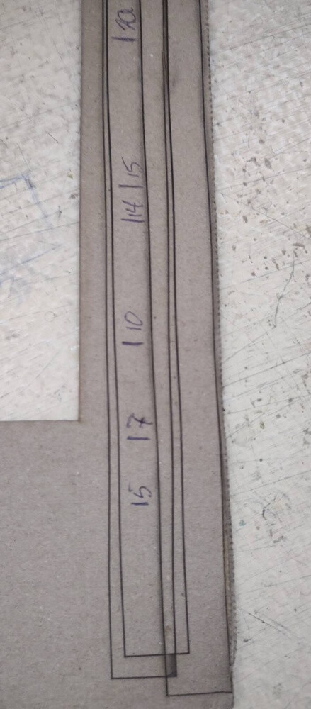
One more thing I noticed during test cuts: when cutting along the X-axis, the lines are wavy (jittery), but along the Y-axis, they are perfectly straight.
This confirms that the Y-axis gantry (which is heavy) is not moving smoothly or is racking due to the single driver setup. This is exactly why I want to separate the motors to two independent drivers to stabilize the movement.
By the way, I have already tried flashing FluidNC once. After flashing, the MKS screen remained blank (no image), and the motors did not move at all.
I suspect this happened because I didn’t have a proper config.yaml file for the MKS DLC32 V2.1 with Dual Y setup. If we go the FluidNC route, I will definitely need a working configuration template, as I’m mostly worried about the motor pins and the screen setup.
In a quick summary because I have to go to work,
I admire your setup and a question that comes to mind is whether the board has the capacity to manage drivers for the motors needed to move, accelerate and decelerate the inertia due to the weight (mass) that must exist. But, again, I’m not an expert on the subject and I may be wrong.
I have installed the firmware several times during upgrades I’ve done on my machine, but it always comes from MKS, and I know that issues like the display not working may very well be related to the installed firmware. Each firmware version has one or more specificities that were developed exclusively for a particular purpose.
As for FluyidNC, I’ve heard it’s a more comprehensive firmware, but I’ve never installed it. However, as I mentioned before, there are people here on the forum who use it.
I hope you can give me some guidance in solving your problem.
Thanks for your kind words, Kuth! You are right about the inertia – that is exactly why I’m moving to dual drivers on the Y-axis. The MKS DLC32 V2.1 hardware is capable, but the stock GRBL firmware is the bottleneck.
Since you mentioned there are FluidNC experts here, I’ll wait a bit to see if anyone can share a working config.yaml for this board. My main goal is to sync the Y1 and Y2 (Z-slot) motors and hopefully get the TS35 screen working, although the motors are the priority.
If anyone has a template for MKS DLC32 V2.1 with Dual Y, please share it!
Usually indicates there is an issue with the X axes. Being not square won’t cause a wiggle, it may be off but only structural stability causes this … I.E. something loose on that axes. If you have this now, it will still be there after you square the machine up.
If Y is straight, then X is the issue. I don’t follow your logic.
What they did in my machine was use one double ended motor with two shafts to either side. Once squared, they must stay in sync.
There is an engineering term from the US Navy referred to as KISS, I think it applies here, but you need to make that decision yourself.
A few years ago, I put my MKS controller into my China Blue, replacing the Ruida. It was just to see if I could get it to work. It did work, but I went back to the Ruida pretty quickly.
I used FluidNC as firmware, but it seems to me using the display broke it, so I ran it sans display.
To be able to use any axes, you must have a starting speed, acceleration and maximum speed to move an axes. Most also contain physical movement length, most axes can’t move forever and remain under control.
Thanks for the info, Jack! It’s good to know that the display might be the issue. Honestly, I’m okay with running it “sans display” as long as the Dual Y-axis works correctly and I can control it via LightBurn.
The mechanical part is ready: I have separate drivers for both Y motors. Now I just need to figure out the config.yaml file. Since I’m using the MKS DLC32 V2.1, I need to map the Y2 motor to the Z-axis pins.
Does anyone have a working config.yaml for this board that I could use as a starting point? I can adjust the speeds and accelerations later, I just need the basic pin mapping to get it moving.
Jack, that’s exactly why I want to use FluidNC. In the config, I can define the Y axis with two independent motors (motor0 and motor1), each assigned to its own step/dir pins (Y and Z slots).
This should allow for independent control during the homing process (auto-squaring), while they will move perfectly in sync during normal operation.
Since you mentioned Lightburn via USB works well, that’s a great backup plan. But first, I need to get the “axes” section of the config.yaml right. If anyone can share the GPIO pin numbers for the Z-driver slot on the DLC32 V2.1 specifically for FluidNC, that would be a huge help!
Here is the visual proof of the issue.
The vertical lines (Y-axis movement) are smooth and straight.
But look at the horizontal lines (X-axis movement) — they are wavy and look like “steps”.
This happens because the heavy gantry is not held firmly by a single motor/driver setup. When the X-carriage moves, the gantry vibrates or racks. I am convinced that moving to a Dual-Y setup with independent drivers via FluidNC will solve this mechanical resonance.
Still looking for a working MKS DLC32 V2.1 config.yaml to map the Y2 motor to the Z-driver slot. Any help is appreciated!
Judging from the hardware in the pictures and the long “wavelength” of those wobbles, it seems much more likely those (3D printed?) slabs are flexing or the rollers tilting in the extrusions.
You can test for that by positioning the head in the middle of the platform, turning the laser on at a low-but-visible level, then pushing the top / bottom of the laser head with a fingertip. If the focused spot moves at all under moderate fingertip pressure, then the mounts aren’t stiff enough.
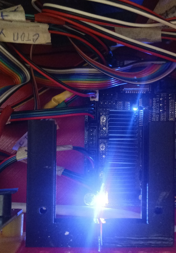
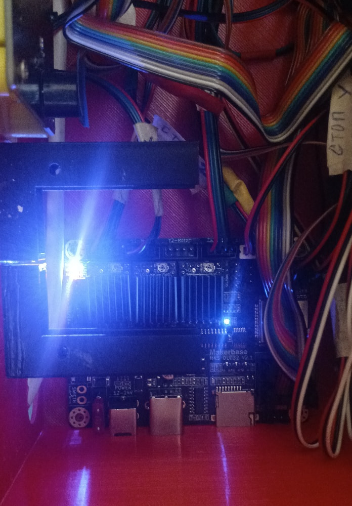
Quick update: I’ve tested the board with the stock MKS firmware, and it works perfectly. All motors move, which means the hardware and the Z-driver slot are 100% functional.
The issue is strictly with FluidNC configuration. When I flash FluidNC, the board becomes unresponsive because I don’t have the correct config.yaml for this V2.1 revision.
Can someone please provide the exact GPIO mapping for the Step, Dir, and Enable pins for the Z-axis slot on this board? Once I have those, I can finally sync my dual Y-axis.
Thank you for stepping up and helping, and for the clarification´too!
But what I was referring to was, extrapolating on the subject, whether the PCB construction (the tracks, for example) can handle the power (Amps) needed to power the motors.
The truth is, I have no idea what current is needed to power the motors, nor the limits of the MKS DLC32 board. This information must exist somewhere, but I haven’t looked for it yet, to be honest.
There are a number of stepper motors from NEMA. If a pcb trace is under question, you need to find out who manufactured it and what weight (in oz) the traces are. Normally a single ounce pcb can only carry 1/2 the current as a two ounce pcb. The weight is based on the amount of copper on specific area of the board.
I think I posted the link to GitHub that has all the information about the DLC32.