MKS DLC32 V2.1 no Laseroutput

Hey all together,

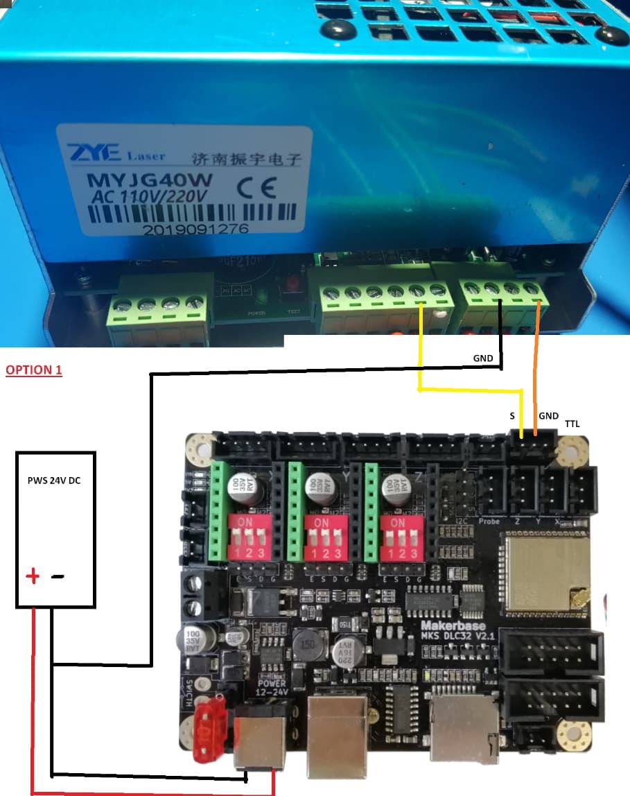
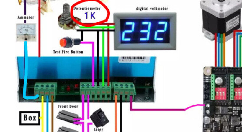
I am currently trying to run my K40 with Lightburn. The motors and sensors are working fine, but unfortunately not the laser. For some reason I have no output on the laser, I have connected L of the PSU to Spindle - and both GND of the MKS DLC32 and PSU. Unfortunately I don’t get any output, does anyone have a guess what the reason could be? Is there anything that needs to be set in Lightburn inital?

Attached are my parameters.
$1=25

$2=0

$3=5

$4=0

$5=0

$6=0

$10=1

$11=0.010

$12=0.002

$13=0

$20=0

$21=0

$22=1

$23=7

$24=300.000

$25=1000.000

$26=250.000

$27=1.000

$28=1000.000

$30=1000.000

$31=0.000

$32=1

$38=1

$40=1

$100=160.000

$101=160.000

$102=520.000

$103=100.000

$104=100.000

$105=100.000

$110=6000.000

$111=6000.000

$112=6000.000

$113=1000.000

$114=1000.000

$115=1000.000

$120=500.000

$121=500.000

$122=500.000

$123=200.000

$124=200.000

$125=200.000

$130=450.000

$131=450.000

$132=50.000

$133=300.000

$134=300.000

$135=300.000

Many thanks for your help

The lps (laser power supply or high voltage supply) has two basic control lines. This excludes the P input which is for coolant flow protection.

The IN pin, controls the lasers current limiting. This can be a pwm or a dc control voltage. On a K40, it’s commonly the pot or current control knob that sets the voltage.

The L input, which is active low or inverted H, is for enabling it to lase.

When L goes low the tube will lase and limit current relative to the control voltage on IN pin.

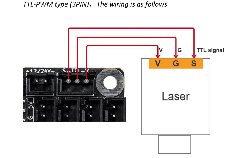
How are these wired on your machine?


The P input must be held to low (or to ground) to tell the lps that the tubes coolant is flowing… On my machine, the controller handles this, so it’s wired directly to ground.

Make sense?

:smile_cat:

Ill tried 2 Setups how i wired but neither worked.

Once shown in the Picture 1 and once i wired The Spindle Minus to L so nothing with P like in Pic 2

However, if I connect P+ to GND I will have a permanent laser pulse or not, P and GND are connected via the TestFire button by default?

You (I) really need to know what pins you are connecting. This appears to be your lps and psu.

The MKS-DLC32 pdf shows the laser connected this way for a laser module.

These are the control signals you need to drive the lps. The pwm signal is generally applied to laser enable or the L input. These grbl boards do not have a laser enable…

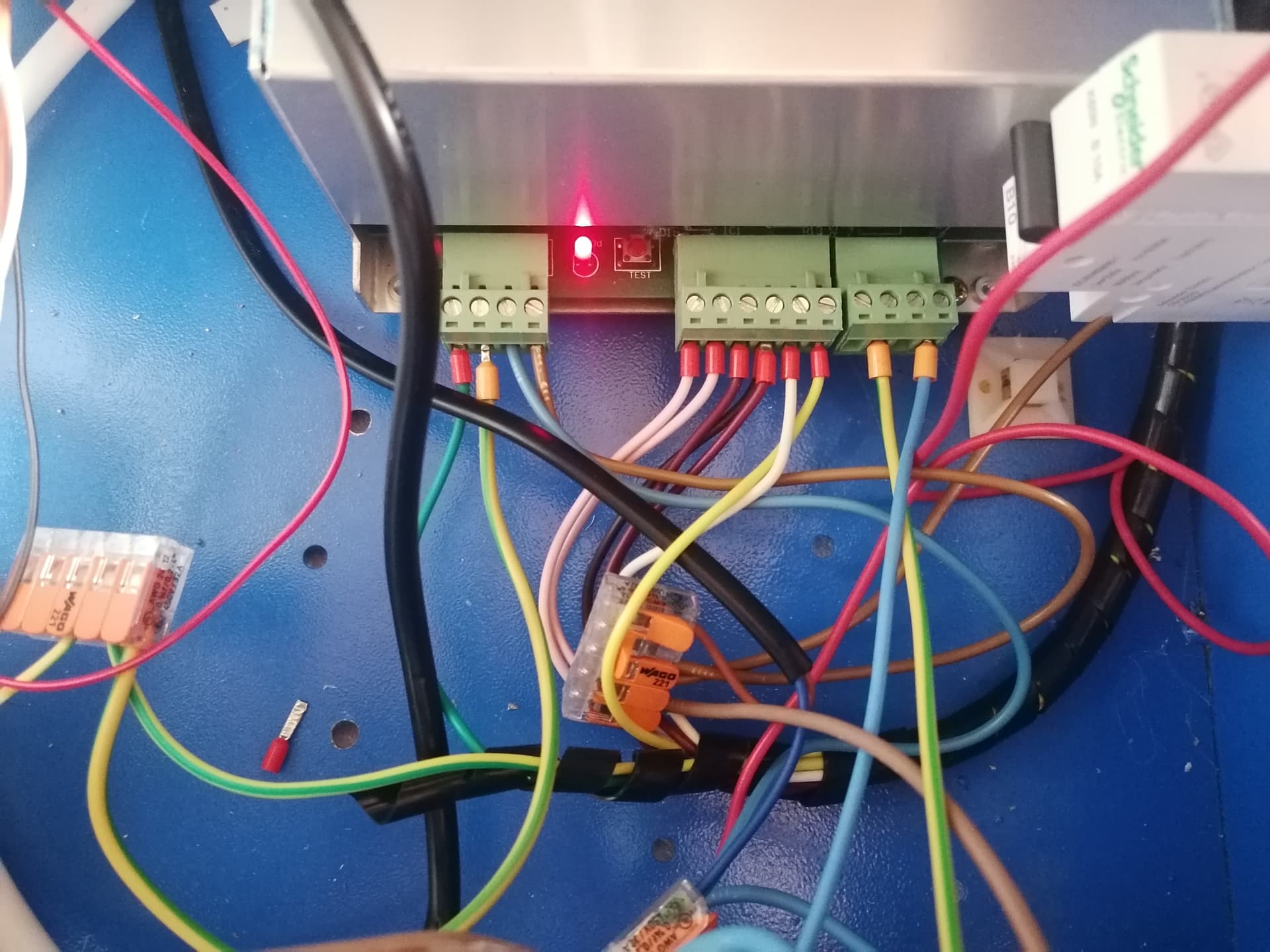
There is nowhere you show how you are really wired… if you only have two wires to the lps, it’s probably not going to work properly.


I suggest you stay away from the spindle interface, it will put whatever the supply voltage you are using on that output…

:smile_cat:

At the moment i wired the V pin to IN and TTL to GND nothing more what shall i connect more?

P to G is conmected via a button for testfire ans P to L is connected for enableing zhe laser

G and 5V are connected to the poti where normaly the In is comnected too.

But it doesn’t work

I read something from inverting a signal with a transistor can you tell me how i need to wire it correctly sadly i dont find anything proper

Wiper from the pot goes to the IN pin of the lps.

The pwm is the issue here…


The 2nd photo/wiring, shows the - spindle going to the L input…

This shows the spindle connector as J7, but I can’t find it on the schematic.

If J19 or J20 is the spindle, you can probably wire the spindle to the L input… it is an inverted pwm, as far as I can tell…

I think you should follow the complete diagram, 2nd photo that shows the fire button and so forth…

If that doesn’t work, we can debug your wiring.

Make sense?

:smile_cat:

So spindle minus is at least connected to the drain of the mosfet.
So you might be right.

So you mean I should connect spindle minus to L and the center of the potentiometer to IN?

That was my default configuration at the beginning unfortunately that didn’t work.

I can use the test button to short circuit P and G
However, ligthburn does not control the laser this way.

That’s the correct wiring I believe, we should look at the other signals to the lps to ensure you have everything enabled for the lps to fire…

Do you have a voltmeter and can you drive it?

:smile_cat:

Yeah i have everything

This isn’t the way the diagram shows… do it like the diagram shows…

Then these signals can be easily check when you have it wired up…

Get it back to the diagram with the spindle output, if it doesn’t work correctly double check the wiring…

Shout if it still doesn’t work and we’ll chase it down with the voltmeter…

:smile_cat:

Na it doesent work what i think is strange, the normal Voltage on the Spindel minus is 23 ish Volt, thats in my opinion fine, if i try to Laser something it just go down to 16 ish Volt i thougth it should go to 0

So if the MKS is not connected L to Spindle i have 0 Volts on L when P and G is shorted and 4V if its open, when i connect L to Spindle i have 16 V while a Laserjob an 23 when “Idle”

What do you mean now i am confused shall i go over the TTL Connector or the Spindle minus to L?


This is the wiring at the moment spindle minus to L and pot to In

There appear to be 2 L inputs, both of which you have wired…

I assume it’s firing when you power it up?

:smile_cat:

This topic was automatically closed 30 days after the last reply. New replies are no longer allowed.