Hi all!
LightBurn has an excellent tool LightBurn Material Test. It has the option to choose a dependency on Q-pulse. But I don’t understand how this can work, because in the JPT MOPA there are only certain pulse width values, for example, 2, 4, 6, 9 ,20, 45 ns and so on.
Question - what is actually sent to the laser as a result of this test, what are the values? If the values do not correspond to the passport values, will it harm the source?
Been wondering about a number of things in the manual, this is one…
It does imply it’s variable so you can use 1 through 500nS… for the q-pulse…
Elsewhere it states this… Not sure how they relate…
If you use the material test, you will see that the q-pulse does make a difference and appears to be fully adjustable…
I’m sure it won’t let you harm it… it has reflective sensors so it will reduce power…
![]()
Hi!
Only some pulse values are explicitly listed in the laser passport. And it is written separately, then additional pulse widths can be made to order. The pulse width of the MOPA laser cannot take any values. In EZCAD3, for example, completely specific values for the pulse width are set in a special ini file (LaserPW.ini). And the program offers them to choose from.
This isn’t the same hardware on EZCad3, it isn’t supported by Lightburn. Doesn’t mean the source is any more capable… However if you use values other than what’s specified, you can see a difference… So I’m not sure how it’s handled…
I don’t have a LaserPW.ini that came with my system… how is it handled with EZCad2?
Maybe someone @LightBurn can clue us in on what’s going on … exactly.
![]()
I have several lasers and I’m going to switch to LightBurn where EzCad2 is installed. As a result, it turns out that everything will have to be tested independently. It seems that galvo has been supported for a long time, Material Test is very usefool tool, has there really not been such a question as I have, what to do with the preset pulse width values in MOPA lasers. It’s strange. It’s hard for me to believe that the producers of this wonderful program do not know such nuances and do not take them into account.
After all, it is enough to make an external file with the set values, and in the process of selecting the pulse width, follow these values both in setting the details of filling in the engraving, and in other places. Otherwise, I will have to print out a plate with these values and periodically check with it to set the hatching values.
We don’t know this until they answer us…
What happens in EZCad3 when you set it to something that isn’t one of the specified values…?
I’ve had this question, but we’ll have to wait for the people who deal with it…
Maybe @JohnJohn can assist us…
Give them some time…
![]()
Due to the fact that there is a file in EZCad in which these values are written, it is impossible to choose something else in the program itself. Only those values that are pre-recorded during the installation and configuration of the system. They are taken from the passport to the laser. There is no such thing here in LightBurn, and theoretically I can set any values. But the laser will not give any pulse width, there is uncertainty of its behavior. I’m not sure I want to test these incorrect values on my device ))).
This is an example of a pulse width parameter setting file.
[JPT]
COUNT=15
VALUE1=2
VALUE2=4
VALUE3=6
VALUE4=9
VALUE5=13
VALUE6=20
VALUE7=30
VALUE8=45
VALUE9=55
VALUE10=60
VALUE11=80
VALUE12=100
VALUE13=150
VALUE14=200
VALUE15=250
NAME1=2ns
NAME2=4ns
NAME3=6ns
NAME4=9ns
NAME5=13ns
NAME6=20ns
NAME7=30ns
NAME8=45ns
NAME9=55ns
NAME10=60ns
NAME11=80ns
NAME12=100ns
NAME13=150ns
NAME14=200ns
NAME15=250ns
I think we’ll have to wait until we get it from the horses mouth, so to speak…
I run mine at anything I choose … To damage the machine doing something like this wouldn’t happen… it’s either changing to a valid value within the range or not… either way, they’d have a lot of these back at the shop to fix.
![]()
Here I found in the passport for JPT-YDFLP-E-60-M7-M-R
The parameter of this instruction is the binary value of pulse width. The user can compile any pulse width, but the laser only accepts the specified pulse width(refer to the specifications of various versions for specific pulse width). If the given pulsewidth is out of the range, the laser will output with the close pulse width value.
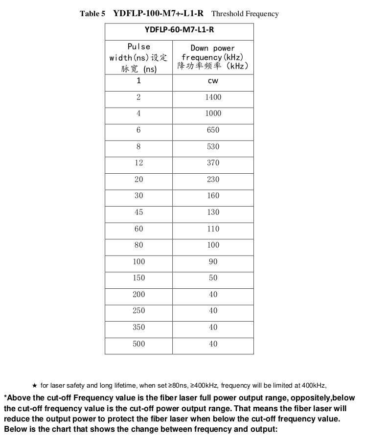
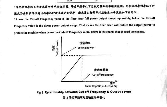
The way I understand it the threshold frequency chart above shows at what frequency/ pulse combination you would have to have to be at full power. The M7 is variable like you said. For example if your pulse was 100, and your frequency was less then 90, the power is reduced. If you find the whole page the frequency chart has a graph on the bottom makes it a little more clear.
This topic was automatically closed 30 days after the last reply. New replies are no longer allowed.