I deal with electronics boards that are built on 0.1 inch pitch strip board. So I would like to specify the distance between between some holes in increments of 0.1 inch, so that they line up with the strip board.
I have almost got this working. It works for long distances like 3 inches. However, for shorter distances like 0.8 inch, or 8 holes on the strip board it doesn’t work. This is because of a lack of precision in the software.
Now, if those precise coordinates don’t produce precise spacing on the machine, then there’s a mechanical problem lurking out there. This test pattern may be useful to track down the issue:
Scale it uniformly to fit the platform and run it as fast as it will go in Line mode with optimizations turned off and power set to mark a sheet of cardboard. Any differences from the design will be informative; a photo will let us look over your shoulder.
Always use something cheap like cardboard until you’re certain you’re getting the results you want.
Thanks for all your input. Sorry about the delayed reply, but matters domestic intervene.
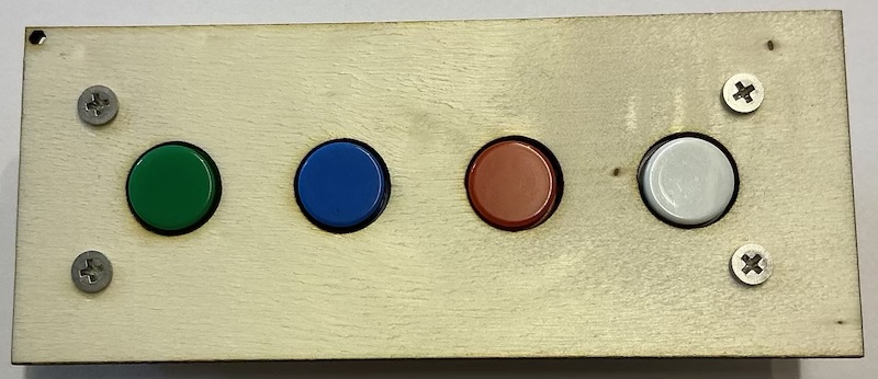
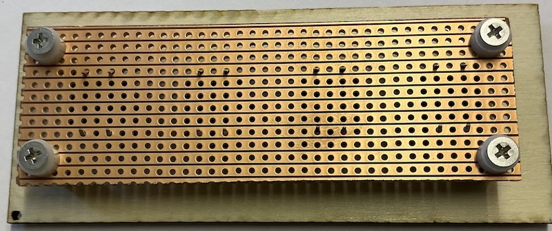
First of all what I am trying to do. Well I have an gallery of component templates to use when cutting boxes. One of these always needed a bit of hand fettling (manual intervention before it would work). So for example I would have to put a file through some holes to make them bigger, file out some small holes and so on. I used to use a special sort of offset pillar that came in a mixed box of spacers that I got from eBay from a source in Ireland. But I can’t find that box to get some more.
I decided I wanted to make my component template work properly. This was tricky because the problem involved using 0.1 inch pitch strip board.
Anyway here is the solution I came up with. As you can see in these two pictures it works.
As I said the holes need to line up the holes, so I used the shift increment tool in Light Burn to define movements in 0.1 inch (that is 2.54mm) with no snapping to the grid. Somehow the other position increment tools would not work.
So armed with this tool I was able to make adjustments that worked on 0.1 inch increment.
Now my laser cutter, when cutting holes, will cut cones. That is the top of the hole is not the same diameter as the bottom of the hole. For a 3mm hole in 3mm material I had to add 0.16 to the size of the hole, and for 4mm thick material I had to 0.213mm to the size of the hole.
Unfortunately on my original template I had made the holes by smaller by this amount. So this needed correcting as well.
I did use cardboard to get this right but this was only 2mm thick and so did not work as well as 3mm wood does. But as you can see this worked out well. There were a lot of other wrinkles as well but I think that gives you a flavor of what was going on.
So I will mark this as the solution, but if you want to know more feel free to ask.
Thanks again.
By the way the pictures are from my new Ipad mini and were in the .HEIC format. I had to convert them to jpegs before I could down load them here.
However, on the Arduino Forum, where I usually hang out, they accepted them without any bother. Which is odd because both forums are based on the same, soon to be changed, to be uncompatible. Which is why I got a new iPad.