Hi. Newbie to the forum.
Just finished building my 1200mm by 600mm 100 watt laser using AWC708c controller and Lightburn software.
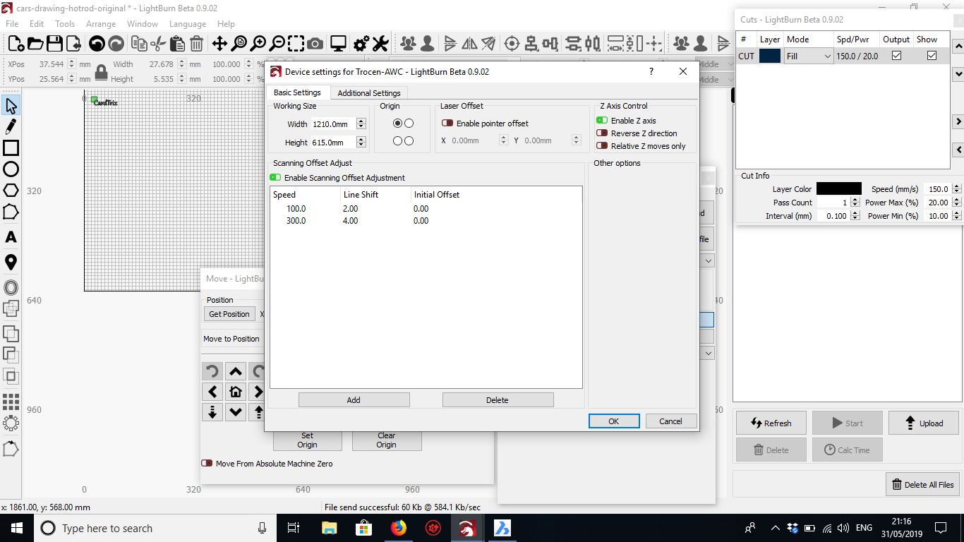
Cutting works fine and I have no problems there. I do though have problems with scanning getting double images so obviously need scanning offset adjustments. I have followed the Lightburn instructions and drew a 50 x 10 rectangle and set machine to fill and I used 0.75mm scan lines. Speeds were adjusted from 100mm/s to 300mm/s in 50mm/s increments.
Differences in line shift were 2mm at 100mm/s and 4mm at 300mm/s increasing at 0.5mm per 50mm/s increase.
I set the speeds and line shift measurements in device settings using 100mm/s and 300mm/s then ran another test rectangle at 200mm/s. Absolutely no difference. Tried entering all the measurements I made and that made no difference. Whats weird as well is when you upload it to the controller or press run in Lightburn, you get the image on the AWC708 screen showing all the lines with line shift so what you see is what you get.
I have been over and over settings and I cannot see anything else I may have missed. Anyone have any ideas please?
Try using negative numbers with the offsets. Are you seeing no difference at all, or is it making it worse? I would expect there to be some visible change in the output.
I did this EXACT same thing today. I used calipers and measured the mismatch and punched in that number
When I re-ran the squares, it looked the same and measured about the same. I took a close look and noticed it was now on the left, but was to the right when on the first test.
So I entered 1/2 the difference and it was about perfect! I only used the line shift, not sure what the initial offset setting does. Good luck!
That is for shifting the whole scan left or right, if it doesn’t match up with an outline of the same shape.
Gotchya - is the 1/2 of total offset expected? Mathematically it makes sense if the coding doesn’t take it into account.
Thinking about it, yes, it would be. The numbers are used "raw’, so if you measured the offset at 2mm, and entered 2mm, it would shift the first line by that, then the second line by that, and end up doing the opposite it did before.
I’ve never actually needed this feature on any of my own hardware, so it never occurred to me that it should use half the measured amount. I could change that.
It would be easiest for the end user if it were compensated in code - measure it and type it.
Otherwise, it might be ok if it was well noted on the documentation and perhaps tool tips in the window.
I agree, I just have to do it in a way that doesn’t break the settings for people already using it. Shouldn’t be that hard.
Thanks for all the replies.
Biology Ben was right. Set half the total offset.
I found it best to only enter 2 ranges of speeds. I used 100 and 300 mm/s. When I used more I found it still was not quite right. By using the high and low range I then did a test in the mid range and fine tuned the high or low offsets untill I got a good cleand set of lines at all speed ranges.
Did lots of tests with images and it looks spot on now.
Weird point though, The image on the controller as the laser is engraving is a double image and not a clear image. Its as though the controller is using the 2 offsets to create a double image. Any ideas on that one?
The image on the controller is a double image because that is exactly what you are sending it.
What ends up getting burned onto the wood doesn’t have those offsets because the offsets are compensating for mechanical slop or a delay in firing from your power supply. There’s no way the preview on the screen can know that is what’s happening.
Basically you’re sending data that is ‘wrong’, in the opposite way that the machine is wrong, so they cancel out and make the output correct.
This topic was automatically closed 14 days after the last reply. New replies are no longer allowed.