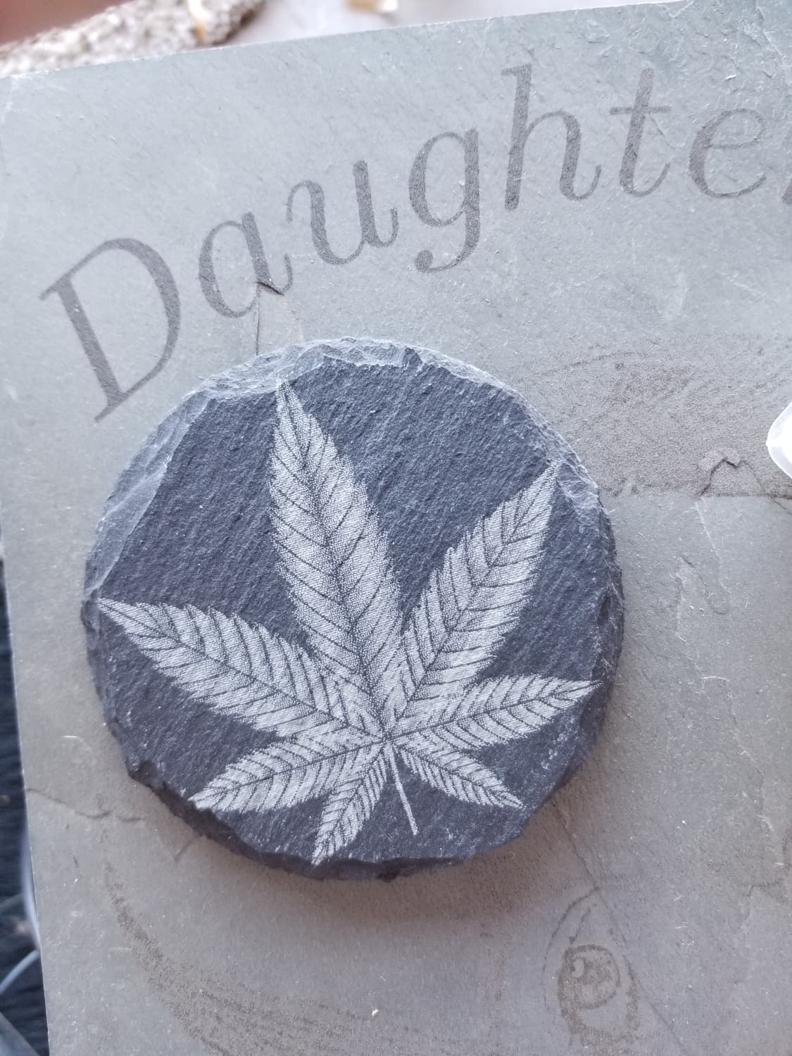
More tests with the new 30w diode laser

Been doing a lot of messing about this afternoon, again. This time basically trying to see if I can get good results at much faster speeds than I have been using. Most of this is on slate coasters, ignore the four dots, that is where I removed the rubber feet so I could use the back sides.

I find it incredibly frustrating that images with very similar grayscale ranges and contrast on the same material can have vastly different quality output given the same settings.

These are all grayscale images engraved using grayscale mode.

First pic is a bass with the image negated and then not negated.

Second pic is the same bass closer up.

Third pic is same bass this time on black acrylic. One on the left was done with transfer tape in place, on the right was without the transfer tape. Don’t be fooled by this picture, it looks good here, but in person you can barely see the fish. The camera in my phone just enhance the light bouncing/reflecting off the grooves in the plastic.

Fourth pic back to slate doing some mountains with slightly different settings.

Fifth pic is a doggo. That weird area on his lower jaw is the laser starting to engrave the bass over the top of the dog.

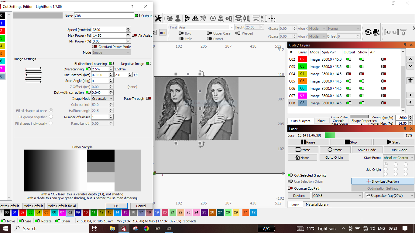
except for the mountains these are the settings used
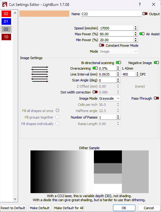
4 Likes

Two things to add here:

  1. slate is a natural material, and as wood, no piece will be exactly the same as the next. Results will only be the same on artificial materials like acrylic and anodized aluminum, for example.
  2. what’s the baud rate you use to connect to your laser? Be aware, that if it’s 115,200 (very common) you can’t reach 17,000mm/min at grayscale, because the data can’t be transmitted fast enough. The bandwidth limit is about 7000 mm/min. Going higher creates unpredictable results, since the speeds change with the image contents (higher contrast areas will run slower than low contrast areas). 400 DPI also sounds very high for a 30W laser, it’s more likely to be half of that.
2 Likes

From my understanding of grbl, the overscan should be enough to reach speed before the image.

You’re overscan is only 1.4mm, not knowing your acceleration value ($121), I’ll be using an acceleration rate of 1000mm/s^2 it takes almost 40mm to reach the specified speed of 17,000mm/m (283.33mm/s). Even increasing the acceleration to 5000mm/s^2, it takes about 8mm to reach that same speed…

I don’t know grbl well enough, but my dsp ignores a minimum power value if you are scanning. Because a dsp computes it before the job runs, it assumes the head is up to speed by the time it needs to lase. Minimum power is only used in vector engraving/cutting. I think @misken will correct me if I make an error here.

As a general rule, if the material is dark or black and the laser leaves a white mark, you need to use the invert option. Some types of slate mark white, some dark. Both of these are different types of slate.

As @misken pointed out, all of these materials, so far, are natural and every one varies from the other, just like anything that nature is growing or creating. Rocks are included with this.


I wonder about using grayscale. It is the most difficult to use. Different materials (sometimes the same material) vary in how they react. Usually it’s used to produce a range of depths.

If you want a grayscale, then the material has to be able to have the type of destructive machining to reflect the complete range of your photo. Most materials don’t. If your wood starts to change color at 42% power and it burnt at 60% power, then you only have a possible grayscale existing between about 40 and 60%… to exacerbate it even more, it’s very unlikely to be linear from that 40 to 60%.

Even varying depths sometimes don’t show up well. I’d suggest you use a dither of some sort instead of the grayscale.

What resolution you can attain is really the relationship between the tool size (laser) and the size of mark left. If you have a beam 1 inch in diameter and when it strikes the material, it leaves a 2 inch mark… your best resolution is 1/2 dpi, even though the beam or tool is smaller..

Make sense?

Nevertheless, love the puppy and the inverted fish :tada:

:smiley_cat:

1 Like

Minimum power setting is 9nly available to me when in grayscale mode on an image layer.

Dpi is way too high.

I don’t know what your dot size of your laser is, but I use 10W laser that has a dot size of .08mm. And my max DPI would be 351, but I usually use 254.

A 30W laser has a larger dot size. Lower your speed and DPI. Look at Lightburn Documentation about how to set your laser settings for photos.

1 Like

Just a clarification, it’s not based directly on the spot size, best resolution has to take into account the damage that spot does to the material.

If you have a 0.10mm spot size, but when it lases it leaves a 0.20mm damage area. You best case is the interval of 0.20mm, not 0.10mm.

:grinning_cat:

2 Likes

I agree with you 100%. I was making a point as to his settings.

He said he was using a 30W laser at 17,000 mm/min @ 400 DPI with max power and min power of 20.

The only part of his settings that are at a good place to start are his max and min power settings.

I don’t see using a grayscale image on slate a good idea either.

Slate is one of those material that has a binary surface. It either marks or it doesn’t, shades of gray are next to impossible to achieve, choose one of the dithering modes will produce the best image.

Reduce speed and power if possible, and definitely lower the DPI.

3 Likes

I guestimate my 20w dot at .1mm and the 40w dot at .14mm. If I had a 30w diode, 0.12mm dot diameter would sound reasonable. That would translate to 212LPI with no overlap of the passes, at best for the slate. Any higher line count is just double cooking it.

1 Like

Hi all

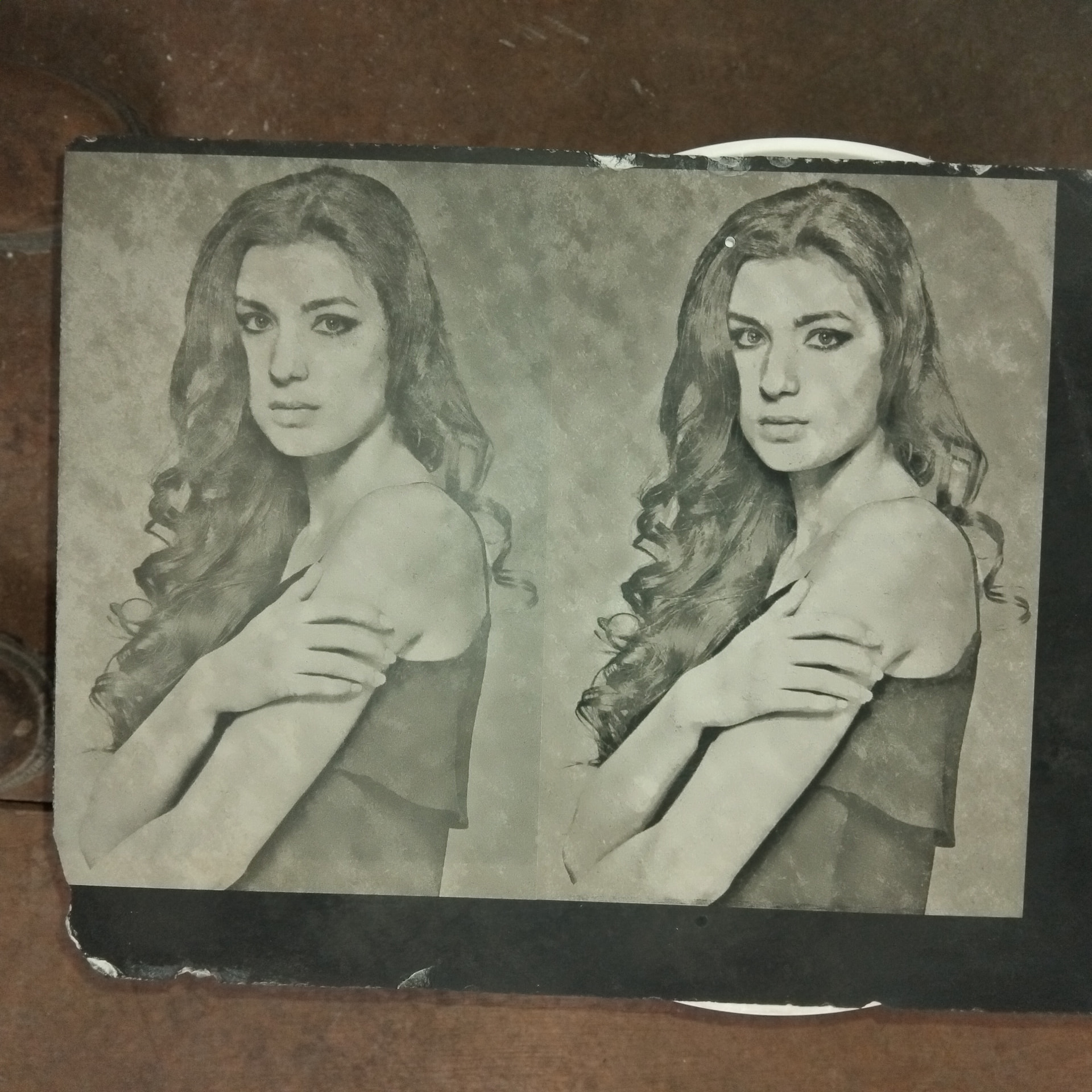
I did these yesterday. The slate has been sanded to remove a previous engraving so the skin has a blotchy appearance due to the material.

They measure 174mmW x 260.9mmH, each. On natural slate. All processing done in Gimp with no further adjustments in LB

The left image is Dithered (Jarvis) and the right is Greyscale. (Image courtesy of ‘@signaureeditscosignaureeditscosignaureeditscosignaureeditscosignaureeditscosignaureeditscosignaureeditscosignaureeditsco’)

Sorry forgot the screenshot of settings, will post in a bit.

1 Like

My stock co2 has a spot size of 200 microns (~0.20mm), I’d take the 140 micron in a heartbeat.

That is the other problem with diode lasers. The spot size is square or rectangular in shape. Most software I know of deals with round spot sizes.

If the lasers beam is 80 microns going in the X direction and 140 microns in the Y direction, you can’t set the interval of each axes to different values.

Make sense?

:grinning_cat:

True. I think if they rotated half the diodes 90 degrees, that would help a lot.

My 10w diode has about a 3:4 ratio, but the 40w is likely 1:2 like your numbers suggest.

1 Like

If you get the x axis set to where you like. Then you use DPI to set the y axis. That basic all takes care you you dot size issue.

Not sure what you’re driving at here. How do you use the machine if the X axes is set to a specific location?

The basic issue is the spot isn’t round, don’t know anything that will fix that.

:grinning_cat:

1 Like

Because LightBurn assumes square pixels, it resamples the image pixels to fit the grid set by the DPI, so the output to the machine has resampled pixels at that spacing in both X and Y on the material.

Per the doc, the Line Interval and DPI values are related:

DPI is 25.4 / Line Interval

Pass-through mode sets the Line Interval from the image DPI:

Line Interval/DPI will be directly tied to the size of the image.