Moving the laser head away from the workpiece and its risks

Hi, I’m new to laser cutting and trying to avoid some beginner mistakes, while making things comfortable.

I’ve only done a couple of test-runs so far, but already noticed some bad effects of ill-advised tutorials.
For example:

I’ve seen tutorials mention the “return to finish position” and thought it would be nice to do that, as the laser head is always above the workpiece after the job is done and it’s hard to inspect it that way.
But: My honeycomb came with helpers to hold down the workpiece. These stand out and setting the move to finish option just changed x/y directions, leaving the laser head hanging low over the workpiece. Sadly, on the way to its finish position, it got stuck on one of these helpers to hold down the workpiece and dragged the entire honeycomb back with it, damaging the honeycomb slightly in the process.

The tutorials did not mention this risk, so I’m here to find out about other risks and beginner mistakes I should avoid. Sadly, I could not find a page or video about common beginner mistakes, that I should avoid.

In order to do the use-case above safely, you’d have to set the Z position as well. There seems to be no option to do that other than custom GCODE.

Any advise on this issue? Is it even advisable in your experience to do automatic stuff if the laser head does not detect if it’s blocked or not? Maybe I should just do everything manually to avoid these kinds of issues, as every workpiece might have special considerations?

Another question about moving away from the workpiece:
The home button moves to 0,0, but also moves the z-axis up first, which seems like a safer move than the return to finish option.

But how does the “home” button relate to origin and the coordinate system?
My current origin is bottom left, which is 0,0 in coordinates. If I press the home button, the head goes to a position, that is very much above my workpiece, as I usually put it more towards the bottom left corner, since my enclosure is build that way.
Does changing the origin to top right also change the coordinate 0,0 to be in the top right? If so, I guess the only option without changing the coordinate system is GCODE?

My intuition right now would be to create a macro, which moves the z axis up and then moves x/y to 410,410, so that I can do this manually, but with one click. Need to learn GCODE basics first though

Thanks in advance.

P.S.: I know there are multiple questions in this topic. Should I rather split them up into separate topics, even if they are all caused by the same (traumatic :face_with_spiral_eyes: ) experience and somewhat related?

Nobody could sit through the millions of variations about how you can make a mistake as a new user… I’m not a new user and I make plenty of mistakes :face_with_spiral_eyes:

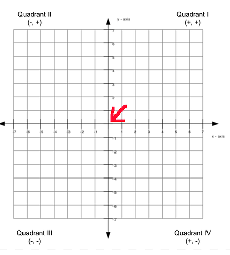
First, understand the coordinate system and how it relates to your machine.

Which corner is 0, 0 is usually called home and that’s where it goes when you press home. When a 3d machine homes, it lifts the Z axes so it will clear the existing work piece and then moves the X and Y axes.

Home or 0, 0 also determines the quadrant in which the machine operates. All machines home at the intersection of the X and Y axes…

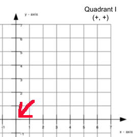
If the machines home is front/left then it’s operating in Quadrant I.

quadrant-i

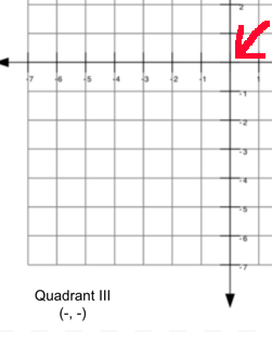
Back/right it’s Quadrant III

quadrant-iii-home

The machine has an machine origin or home location already defined that identifies the operating Quadrant. You must tell Lightburn which corner is home (Quadrant) you are operating within.

There are ways to apply offsets to work from other areas, but I’m not up on the gcode to do this and you’d have to execute it every time the machine restarts or homes.


Then how to control the laser with the start from and job origin settings.

Lightburn documentation on all operations are worthwhile reading and are generally rather short… always read the docs, then ask questions.

Good luck

:smile_cat:

1 Like

If you have a powered Z, using the Z offset in the layer controls will jog the laser up to start height before sending to finish position.

You can set finish position to anywhere. I may suggest setting X to a central position and Y to a limit, that way X always travels away from the workpiece edges where you are likely to secure.

If that still won’t clear, use shorter fixturing. Unless you’re trying straighten thick materials, (which would tweak your bed anyway), you don’t need more than a couple mm clamping thickness.

No idea what your clearance is. Mine is typically about 8mm. I have clamps with thumbscrews into a 2020 bed frame and combined they’re less than 6mm. That’s at the thumbscrews. The clamp arms are steel and less than 3mm, so except at the very limits of my X travel, where the thumbscrews live, I typically have at least 5mm gap between my fixturing and the air nozzle.

1 Like

If you like to get deeper into the matter, I collected some hours of documentation about various aspects of diode lasers. Some are targeted to specific hardware, but most tips apply to all models. There are articles about the coordinate systems, homing, z axis and more :slight_smile:

1 Like

Thanks for the explanation @jkwilborn, I will look at the docs.

@cggorman I have a powered Z (and activated in the settings), but why would I set the z offset in the layer, if there is autofocus? I have yet to find an autofocus, that does the autofocus as part of the job, but that’s another story.

Setting the x center and y to a limit would work if the laser head was small (mine has a protection box around it) and if the job stopped at the x center… I guess I could start all my projects at the x center, but I’m not sure if I can remove the protective box or even want to do that… Even if I could there’s still the laser-crosshair and autofocus switch case, which is at the same height.

My clearance is 8mm and the fixtures are at 7.5mm height. But due to possible z-steps when doing multiple runs, the head might be lower than 8mm at the end of the job.

I will look for, or try to build some fixtures with lower height.

Thanks for the quick replies :heart:

Thanks, bookmarked :smiling_face:

Does the z axis have limit switches at each end? Autofocus is not that easy because you need to know the workpiece height. You can only reliably determine that using a probe sensor. There are other ways if the height of the bed is exactly known in relation to the homing position of the z axis, then you can manually set the z height of the object. The procedure with a probe is described here: Automatic z-axis / focusing - Diode Laser Wiki

1 Like

As Mr. Melvin indicates, if you know your workpiece height, you can set a fixed “autofocus” height that’s much higher than an actual working height then use the layer offset to drop it down X for engraving and X+Y for cutting, plus steps if needed. The head starts at, say, 15mm, moves to start, drops to engrave height, engraves, drops to cut height, cuts, then raises back up the start height before moving to the finish position.

1 Like

@misken I guess I didn’t mention my laser Model :sweat_smile:
I have an Ikier K1 pro, which has a limit switch at the bottom of the laser head and a special GCODE instruction [ESP500] to move down to the workpiece and a little up again just as described on the page you linked, only It came out of the box with the laser.

@cggorman A fixed “autofocus” might be an option, especially when I have a library of materials set up, but I’d always have to take into account if the height difference between the lower layer (where the workpiece rests on) and the laser frame itself is the same.

For example, if the workpiece is bigger than the honeycomb and rests on the honeycombs frame instead of on the honeycomb itself. Or if I lift the laser frame up to allow for a bigger workpiece to be engraved. Not sure if these are going to be real use-cases for me yet. Just trying to get a bit of knowledge, so I have something to decide on.

Anyway, thanks for all your answers. It helps a lot!

There are definitely more variables to manage if you want to use a clearance height and different offsets for each workpiece. It’s a workaround, for sure.

I also have a K1 Pro. I added a 3.5mm positive(up) Z move to the focus macro that gives me a known clearance above any workpiece surface. I then add the offsets to the material library to compensate.

I haven’t had any crashes since adding the Z variables and the low profile fixturing.

This topic was automatically closed 30 days after the last reply. New replies are no longer allowed.