My new OMT-CO2 Laser Machine

Those are beautiful. Nicely done.

1 Like

Thanks
… a small addition of information, in my design I have used some guides which are also cut out. I typically use them to break large pieces into several parts. This makes it much easier to pick them out afterwards. Especially in names, it is not always easy to get that “filling” out.
By the way, I am positively surprised at how well a focal point the standard optics can produce.

Today I have been able to experiment with my machine and different materials again, I enjoy the process. However, I did some hardware work first, I replaced the lid on the left side with a temporary lid, one with an outlet for extraction. The original hole in the rear service lid I closed. The operation is necessary to be able to move the machine to its final destination. In the meantime, extraction runs through a Ø110 pipe system, normally it will be undersized, but with the powerful fan that sits in the system, there is no problem with bad air in my workshop. I’m glad the fan is outdoors, in fact only my CW5000 is making moderate noise ".

I made a test series with 6.2mm HDF and 5.15mm bamboo plywood, the results are satisfactory.

(my test rounds look dark as they are, there is no soot at all and the items just fall out)

But I have found a small problem with my my power settings, or rather, my ignorance of this. For my test items, there are 2 smaller cutouts where the problem is well visible. Although I do not have too much speed, it looks like the laser does not have time to stop to change direction. My attempts to adjust min. power did not give the desired result.

(they are pictures of the back)

Maybe some of you have an idea or suggestion what I need to change to achieve a better result.

It’s always nice to have the .lbrn2 files. It just eliminates that being an issue quickly.

IMHO that ‘darkened’ area is caused by the fumes of cutting. Do they ‘go’ in the direction of air flow?

When I engrave I do it from the bottom up, exhaust in the rear. Cutting is difficult since you are usually have to go ‘around’ things.

There appears to be an offset occurring, if the photo is oriented properly, in the Y axis, but also appears in the X axis. If it’s hardware of software (configuration)…?

As a suggestion, can you measure the hole offset from the inner circle to the outer circle in a number of places to see if the circles a not quite circular. I would think there would be a variance there.

May give us some better hints. I’d also suspect it’s been seen before, just need someone to notice it here. Maybe @LightBurn can give us a clue from their experience.

With a DSP controller, it figures out how fast thing need to go to get around corners and controls the power related to your min/max on the layer. Make sure you know how your controller is configured to handle the switch to min power.

This is not a power related issue. It almost looks like the material has moved…?

:smiley_cat:

I don’t mess with min power much because I’m learning too. I thought I read somewhere that the rule of thumb is roughly 10% lower than max power for min power.

1 Like

It totally depends on what you are doing. If you are cutting, then they are generally set the same with the thought that a min power setting may not cut through in a corner where the machine is slowing down.

If you are engraving something delicate, with vectors you can really control how ‘burnt’ the corners are.

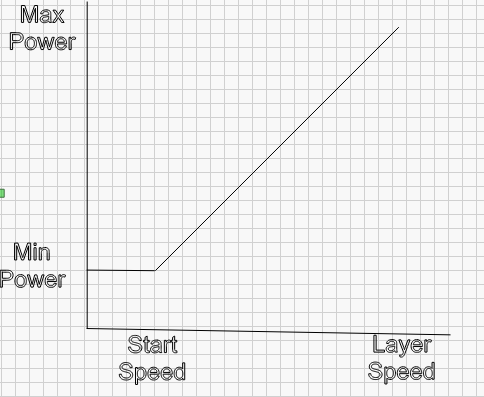
It basically is a scale from the ‘Start Speed’ to the layer speed → min to max power.
If your speed is below ‘start speed’ you will only get min power.

I believe it works like this

Screenshot from 2021-12-09 07-43-44

Here is a pretty clear explanation.

:smiley_cat:

Thanks for the response. The file itself may not be the problem, I have done all the tests with my K40 with the same file that has only replaced the text with the relevant data each time.
I have checked if X and Y are set up correctly, a 100, 200 and 300mm square perfectly holds its dimensions, sore circles are also “round” and hold dimensions, even at relatively high speeds.
Materialtest.lbrn2 (32.1 KB)

“Desc”: “Start speed (mm / s)”,
“ID”: “0x201”,
“Value”: 5

Jack, is that what you’re referring to ?, I have not been below this speed, but does this value not stand a little high?

Assume you looked at the saved file. I don’t do that… Broken too many things that way…

I use the ‘Edit → Machine Settings’ option.

Many have 20mm/s as a default, mine was 25mm/s. I have mine set to 5 also. So assuming you have the right field.

Maybe you should raise it to 20mm/s if you want to use the entire power range…

Make sense?

:smiley_cat:

Thanks for your suggestion, but I’m relatively conservative when it comes to my speeds and think that 20mm / s is far above the speed I use to cut thicker materials. I want to experiment a little more and see if I can find the optimal values ​​for cutting small parts.

So today I do not have much time for fun, but I have been able to update my Christmas decorations with a very important part!

You can try to guess which part took the most time. :wink:

1 Like

Is it possible to mount a 3 “lens in the original nozzle head or do I need another nozzle / tube for the purpose? When I” calculate "the angle and distance (76.2mm), the laser beam probably does not fit through the small hole in the nozzle .
I am aware that with a distance from the nozzle to the workpiece of approx. 43mm at a 3 “lens can also not give an optimal air flow. Can I just buy a” lens holder tube "or do I need a completely new nozzle?

Not sure if I follow you completely, but I use the Cloudray ‘C’ series tubes.

Each tube has a different offset from the lens mount to the ‘end’, so two positions for lenses on the same tube. The same tube turned over changes both of those differences. And the nozzle itself can hold a lens.

:smiley_cat:

I must not have been completely awake when I ordered the 3 ”lens without thinking about how to mount it correctly (in height). For a moment I thought I could just swap straight over with my 2 ”lens … but yesterday it finally dawned on me that the height will not fit without an extension piece.
… I’m a little confused about the different nozzle type designations, is the C type the one I should go for with the machine I have?

‘C’ series tubes relate to the diameter as far as I know. I use a 4" on the top of the tube, when inverted I use the 1.5" lens on the bottom.

I’m got a few things to do…

But I’ll go back over the thread and see how your machines head is set up when I get back to it.

This head uses those tubes. This is the compound. I have 6 tubes with 4 lenses mounted in them and a couple of empty spare ones.

:smiley_cat:

Thanks,
I can see that it’s Russ nozzle, I “wish” it for Christmas :wink:

2 Likes

and the Russ mode to flip the belt for smoother movement. I know a guy who just purchased a beta version of Cloudray’s Russ Spec laser cutter and it’s a VERY nice machine. I don’t buy all of what Russ says(red laser is useless) but most of it is right on.

Doug, I think we have the same attitude to Russ, not everything that shines is gold or silver ;-), but he is a very instructive and gracious person. I also think he has done a lot for “us normal laser users”.

That with the reverse belt mounting I have somehow forgotten or missed, can you give me a hint on the subject?

PS. his last lesson, regarding focus has been again an interesting one for me. As I wrote before, My wife watches “Barnaby or Inspector Morse …” and I watch Russ`s “Laser channel” and we both enjoy it.

This <15 min video kind of explains the problem. The ‘rack and pinion’ belt drive was his fix.

I don’t buy into everything, but when the numbers work out, I’m more convinced… :crazy_face:

:smiley_cat:

… Now I can remember. I skipped then and will do it again today :wink: But the man is definitely right, I think.