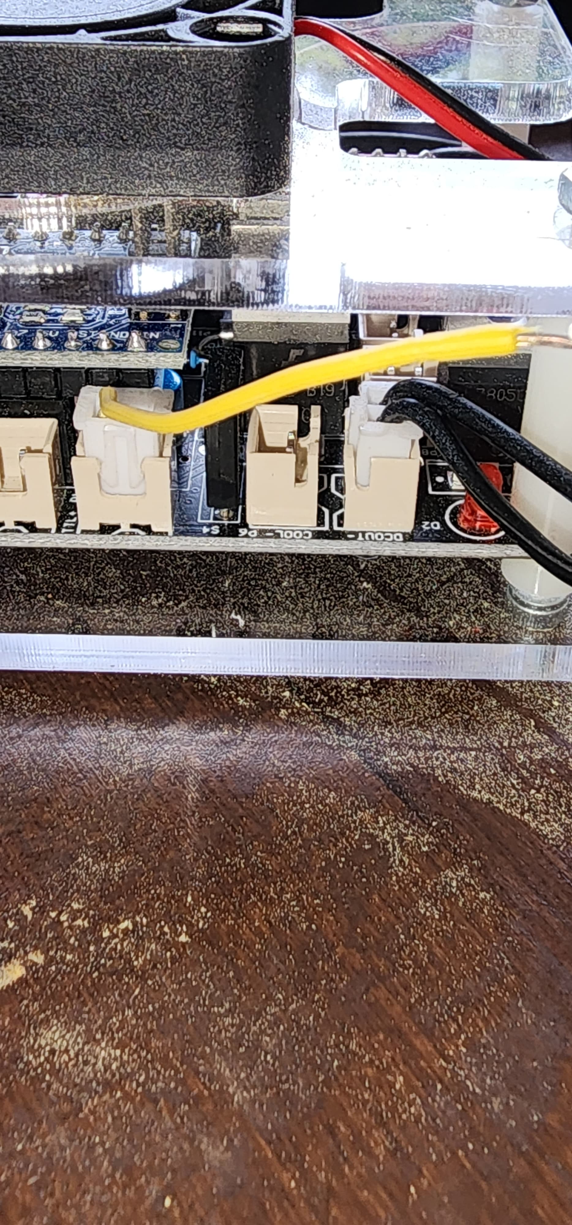
this is the board

and it is a 15w diode blue laser
Your machine is equipped to handle variable power assuming the firmware is compatible.
However, the way you have it wired now it will not work that way. To be clear, you have a 3-pin connector on the module going to a 2-pin connector on the controller. How is it wired?
For this to work I’d suggest you rewire the controller to the laser module:
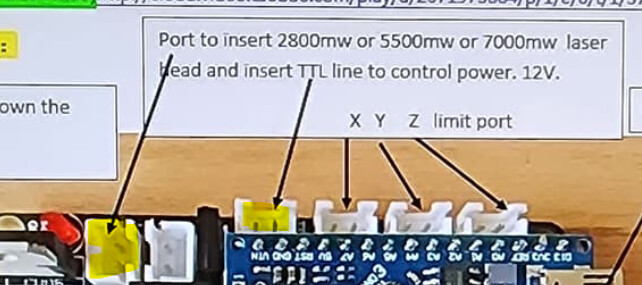
I suggest taking 12V and ground from the yellow highlighted connector here. Also, connect TTL and ground from the controller to the PWM and ground pins on the module. So you will need a method of going from two separate 2-pin connectors to a single 3-pin connector.
Separately, if your laser module is indeed 15W output, it’s possible that your controller is incapable of supplying the current required for the laser module. In that case, you may want to provide power to the laser module separately. You should be able to run at lower power in any case to test this.
If I understand correctly I think that is how it is wired currently
The yellow wire goes to TTL + and the two black wires go to the laser port that you have highlighted and the correct + & - wires going to the laser module. It had a separate wire going to the pwm pin on the laser module so I added the three wires together in the same molex plug. The strange thing it has been wired like this for years and would burn through any wood in lightburn without any problems. It all started when I updated to grbl 1.1
I noticed on this thread you referenced that low power was also a problem, but he seemed to resolve it, but he didn’t explain how.
right I read that yesterday. I am lost at this point
I asked him to explain how he resolved the problem. Maybe he will respond back.
How is your device set up under? Plain GRBL?
Thanks for that I hope he does. And yes version 1.1h grbl
This is what you have it set to in your device.
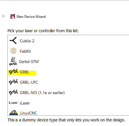
yes I have that selected. What should I have it set on?
I’m going to assume that even though the color of the wiring is different between the board and the laser module that you’re somehow bridging the wires. Correct me if that’s not the case.
In that case I’ll go back to what I was suggesting earlier.
At the TTL/PWM port on the controller, measure voltage there while you’re running at various power levels in LightBurn. That’s necessary to know if your controller is modulating power. Depending on the outcome of that test the issue is likely going to be in the firmware yet or in the laser module.
Yes the color of the wire are bridged. Also I checked with my meter on milivolts and the lightburn setting on grbl the voltage at 100% was between .49444 to .53452mv fluctuating. On the grbl 1.1e or earlier settings at 100% it was only 2.449 mv , 50% was 1.18 mv and 20 % was .890mv
These numbers are very confusing. GRBL-M3 and GRBL should give you the exact same voltage at peak. Not clear to me why you’d be getting different values here.
It’s interesting that the voltages for M3 do seem to scale based on power level although at extremely low values.
Can you confirm that your meter is known working properly? If you check the 12V pin does the meter in fact measure 12V?
Also, try this, test voltage at pin D11 and Gnd of Arduino board at varying power % levels in LightBurn.
Yes Sir I do have 12.58v at the laser port on the board. I checked with two other meters and received the same voltage reading. I then ran lightburn at various power levels and received the same results as posted previously. Just curious is 12v supposed to be always on at the laser port on the board even when lightburn is being used?
Hi Lee,
I had the same issue using the same Laseraxe controller. My firmware got reset and I was struggling to get things to work right again.
I am now using GRBL 1.1f from the link below (download is named 1.1h):
https://github.com/darkez/grbl1.1h_laseraxe.cncc.mini/releases/tag/default_working
Once I used that version jogging was back to normal. Can you verify in the console you are running the correct version? As for the laser power issue, I don’t recall doing anything special except adjusting my speed/power settings, unless the firmware above may have fixed that too. I usually keep power around 50% and adjust my speed, usually below 750. But I will try to think back and remember if I did anything to fix it. I’ll check my setup here shortly.
Below are my current settings
Grbl 1.1f Ready
$0=10 Step pulse, microseconds (10)
$1=25 Step idle delay, milliseconds (25)
$2=0 Step port invert, mask (0)
$3=0 Direction port invert, mask (0)
$4=0 Step enable invert, boolean (0)
$5=0 Limit pins invert, boolean (0)
$6=0 Probe pin invert, boolean (0)
$10=1 Status report, mask (1)
$11=0.010 Junction deviation, mm (0.020)
$12=0.002 Arc tolerance, mm (0.020)
$13=0 Report inches, boolean (0)
$20=0 Soft limits, boolean (0)
$21=0 Hard limits, boolean (0)
$22=0 Homing cycle, boolean (0)
$23=0 Homing dir invert, mask (0)
$24=100.000 Homing feed, mm/min (100.000)
$25=1000.000 Homing seek, mm/min (1000.000)
$26=250 Homing debounce, milliseconds (250)
$27=1.000 Homing pull-off, mm (1.000)
$30=255 Max spindle speed, RPM (255)
$31=0 Min spindle speed, RPM (0)
$32=1 Laser mode, boolean (1)
$100=100.000 X steps/mm (100.000)
$101=100.000 Y steps/mm (100.000)
$102=80.000 Z steps/mm (80.000)
$110=4000.000 X Max rate, mm/min (5000.000)
$111=4000.000 Y Max rate, mm/min (5000.000)
$112=6000.000 Z Max rate, mm/min (5000.000)
$120=800.000 X Acceleration, mm/sec^2 (800.000)
$121=800.000 Y Acceleration, mm/sec^2 (800.000)
$122=5000.000 Z Acceleration, mm/sec^2 (5000.000)
$130=400.000 X Max travel, mm (400)
$131=300.000 Y Max travel, mm (300)
$132=200.000 Z Max travel, mm (200)
12V will be available to the module the entire time it is on. This is partially board dependent. So if there are lights on or fan on that means 12V is going to the module irrespective of whether or not the laser is firing.
Were you able to test voltage at D11 of Arduino?
Your $30 is 255, is that also what you have set in Lightburn for your S value?
Thanks guys for your help I have been on the road traveling. I determined that the board more than likely has failed in some capacity that I am unable to fix code lol. So I purchased a new board. It is a Jadazi https://www.amazon.de/-/en/JADAZI-Controller-Control-Stepper-Spindle/dp/B08P5H8C6Q/ref=cm_cr_arp_d_product_top?ie=UTF8
All I had to do was plug in everything and I added all of my code settings from the previous board and now the laser fires and x & y move correctly. But I only have one problem now is that the image burned is oval instead of round and also illegible. I’m
This is now a very different situation than the original problem.
Based on the output it’s unclear what’s happening.
Try a couple of test burns:
Also, can you upload the .lbrn file you used for the notary test?
Hi, With a new board, you might double check the x/y travel accuracy. Then, the registers $100 & $101 might need values different from old board.