@LightBurn Wanted to post and see if there were any plans to implement native support for linear stages like the Maxce IndexX. I have been able to get the IndexX we purchased from @BetaMax to work by treating it like a rotary but its a bit clunky and would love to see a dedicated tool in Light Burn for these!
Thanks,
Ben
That is a nice looking X table, very low profile for 700mm travel. A lot of thought went into that design. Just curious, what is the part that you consider “Clunky” using the settings in the rotary window?
The table itself is really well put together and is worth every penny I spent.
There are a couple things I’d love to see implemented on the software side to really tap into what it could do.
- You have to hit go to zero every time you open the rotary window before running a job. If you don’t, it will run the job relative to the position the table is currently in, and not the actual origin (far left side of table). You also have to go to zero after running a slice preview for the same reason. Not unusable, just “clunky”
- The slice size and shape size is limited to just under 4" (100mm), i assume because that is plenty for most circular objects, but I am wanting to run long pro audio panels that are 19" wide and I end up with visible transition lines no matter what settings i seem to use.
- If there was a way to basically have a linear stage act almost like a plotter where the beam moves on the Y axis only while the X table moves smoothly back and forth allowing for clean continuous markings to be make on whatever piece you are marking.
I have been able to successfully use the table for repeated markings (multiple small items) and as an extended working space but only when the markings are small and far apart. The breakdown occurs when I want to run a logo or a mark that is very large in width (exceeds the 100mm shape and slice size). No matter what settings I try, I aways end up being able to see either a gap or a very clear white line where the slice occured.
Well thought out response, thanks. If you don’t mind elaborating:
How many steps per mm?
What are your steps per rotation set at on your microstep driver?
Have you tried keeping your slicing small, 1mm-5mm range?
Scanning perpendicular only to the table travel?
One of my current projects is an XY table, have been playing with this stuff for a while, that’s why I ask. So my strategy with my smaller X table projects is small slices keeping the beam more perpendicular, Got some pretty good scans without visible slicing. Another member was in the 600mm range but seemed like LB or the computer was running out of memory, had to reduce his microstep driver settings down to 1600 to solve, my current project I’m using 20mm pitch ballscrews 1000mm X so I’ll have around 700mm +/- usable travel, see if that works.
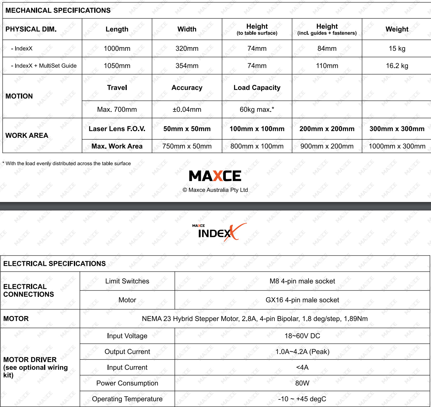
Specs for the IndexX table linked in image.
I tried small slice sizes and was still finding I could make out individual slices (spent hours messing with overlap to no avail)
I have linked the computer I am using for lightburn but I would think it has enough memory to handle the job (16GB RAM). Let me know if you think otherwise. https://www.amazon.com/gp/product/B0CGJ3C8MY/ref=ppx_yo_dt_b_search_asin_title?ie=UTF8&psc=1
You would know if you start running out of memory, LB is really stable but just stops for a while when up against it, amd then picks back up where it leaves off. Really overloaded the rotary before, it comes to a stop, starts back up when the processing catches up. Doesn’t skip a line. Might be the BJJCZ, might be RAM. LB itself doesn’t crash no matter what.
Ok, yeah I haven’t experienced anything like that yet.
What do you have for your rotary settings?
I will take some pictures and screen grabs when I am at my shop next week.
I followed @BetaMax’s setup video pretty closely and matched the settings he notates for an extended work area. I’ve linked that video here: https://www.youtube.com/watch?v=-J6DHxKTJMQ
1 Like
Great video. Well presented. Learned a few things/ reinforced things I had previously figured out trial and error.
At the end, where he shows a 30mm split and run whole shapes if possible “on” with 20mm max size, that is screwy. If you determine the max size of a whole object can’t be more then 20mm, your split or slice should be the same or smaller. Or the other way to look at it, if you determine the split is OK at 30mm, no reason “Whole Shapes” can’t be 30mm. The advantage of a flat table over rotary, your “Whole Shapes” limit can be anything less then your calibrated lens field size.
With the rotary, and applies to a flat table as well, I try to break up the artwork and use the “Whole Shapes” feature when ever possible. Use the ungroup as many times as it takes to get artwork down to it’s individual objects. (Obviously not possible a lot of the time, with long continuous objects, wide ovals, borders, etc.) Put the individual objects on a different layer then the larger items that need slicing.
Also, worthy of noting, any objects that can’t be run as a whole object need to be run with a scan angle perpendicular to the table travel. (Note above, argument for separate layers) Slicing is not compatible with angled scans, cross hatching, etc., even on a flat table. You will (almost?) always see the lines at the ends of the slices.
I try to get everything set up to the point I don’t need overlap, it can only move backwards in 1 microstep increments, regardless of what you put in the field. You can only go forward in 1 microstep increments during normal operation, so if it didn’t stop in the right place going forward, backing up won’t help. Instead of a gap you will get an over burn. Try changing your circumference by very small amounts. Those extra .3333’s and .66666’s that you round off might make a difference over larger areas.
This topic was automatically closed 30 days after the last reply. New replies are no longer allowed.