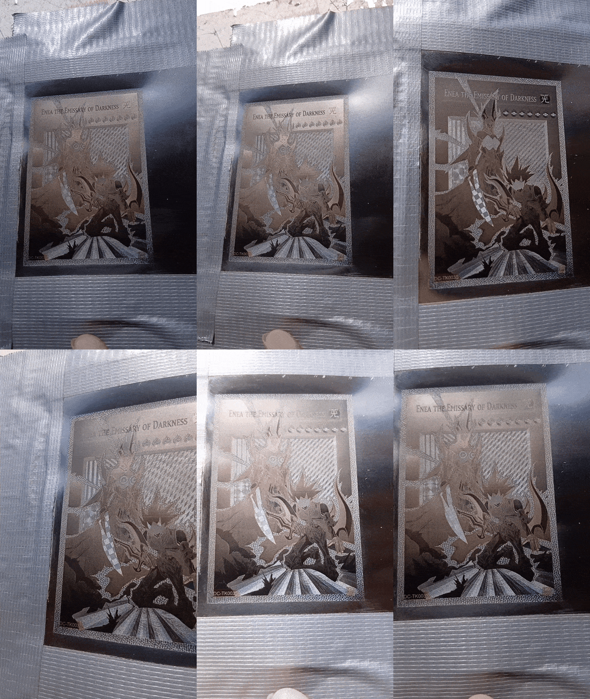
I am trying to replicate Applied Science’s method to create diffraction gratings on Stainless Steel.
I am suffering D:<
Setup:
ComMarker Omni1 5Watt (355nm)
Sheet of Stainless steel
The video in question is this https://www.youtube.com/watch?v=RsGHr7dXLuI
Now a short tldr for those lazy to read the paper in the description.
Incident beam hits the sheet of metal. Electrons thermalize in the process creating a temporary plasma. This makes the dielectric constant of the Steel surface negative, which allows according to the Drude model, for the electron frequencies in the surface to slightly lag behind the incoming EM wave due to their inertia. This will cause interference fringes on the free surface electrons, spreading out the surface heat in microscopic peaks and valleys along the laser dot. The fringe spacing is obviously dependent on wavelength of light (which may be the cause for my failure). So the interference pattern is inside the dot so to say after it is done radiating.
So the whole brunt of the technique actually ignores line spacing altogether (the mechanism you would use for oxide layer growth for colors) and focuses more on line dynamics. The idea is that even a single etched line is going to look Satin Rainbow. And you have to play with other modulation parameters
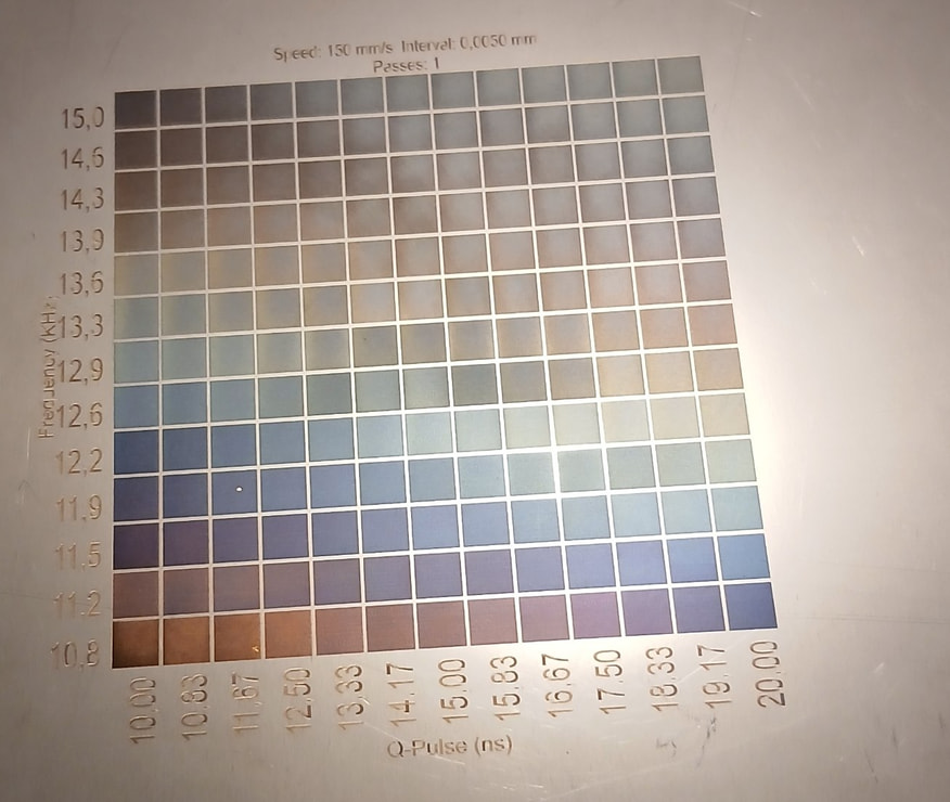
Now the commarker omni1 does not have power modulation, they run at a constant wattage and the amount of fluence you deliver to your material is mostly controlled by the qpulse parameter.
In the video he is using a 100Watt MOPA fiber laser (~1060nm i believe) with what seems to be a wide field f theta lens (from the size he is engraving on).
He runs on 1 micron pitch (When frequency in KHz match the speed in mm/s, each time the laser dot hits, the center-to-center spacing is 1 micron).
Now this is Important. This pitch and the grating pitch are NOT the same. The grating itself has features on the nanometer scale.
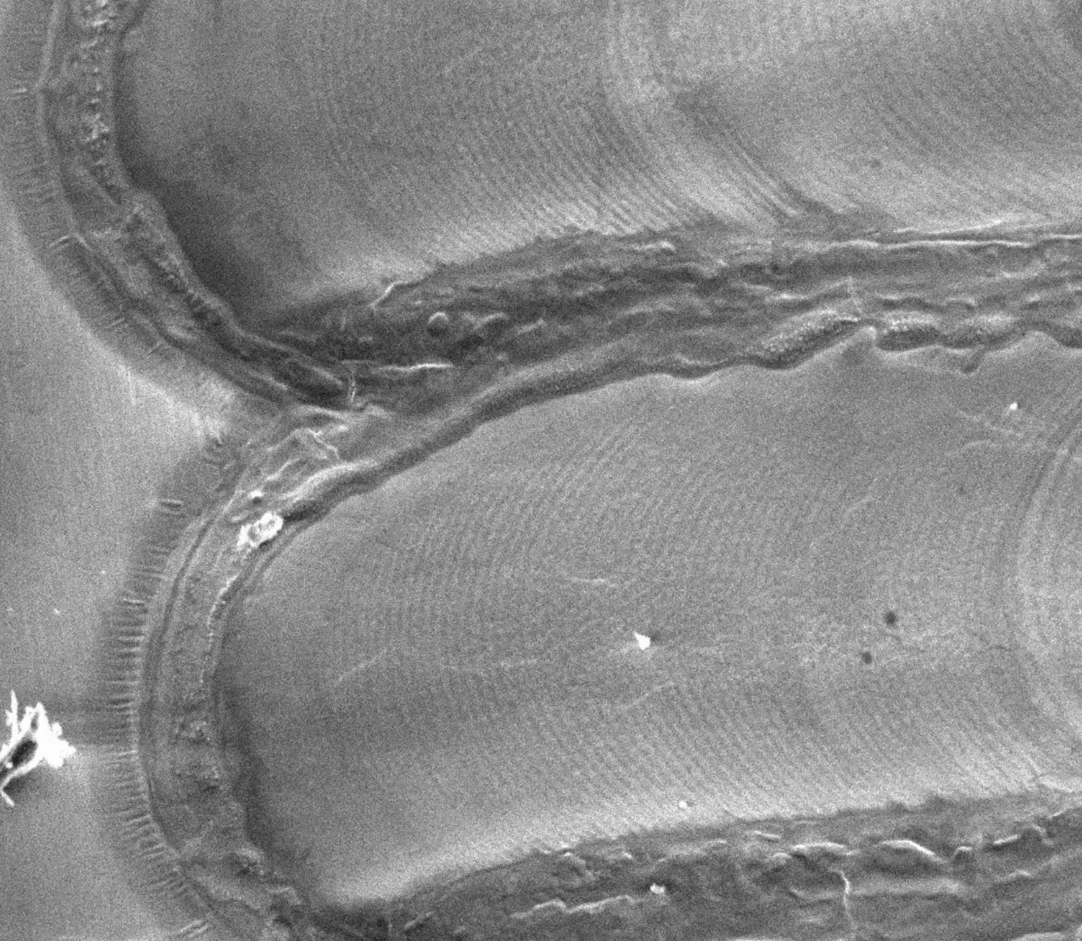
Those small ripples are the fringes and the large blob is the laser dot imprint.
I do not have a SEM to check my steel samples, and i COULD be getting fringes but not of the kind that will diffract in the visible wavelength (if any exist).
However the diffraction equation does not really help me here because i could just be creating fringes that are either too small for the visible wavelength or i am not creating fringes at all.
The guy in the video runs his laser at 300KHz which gives very low exposure times (unlike my maxed out at 40KHz) and causes the metal plasma to not cool down in time before the next time hit comes.
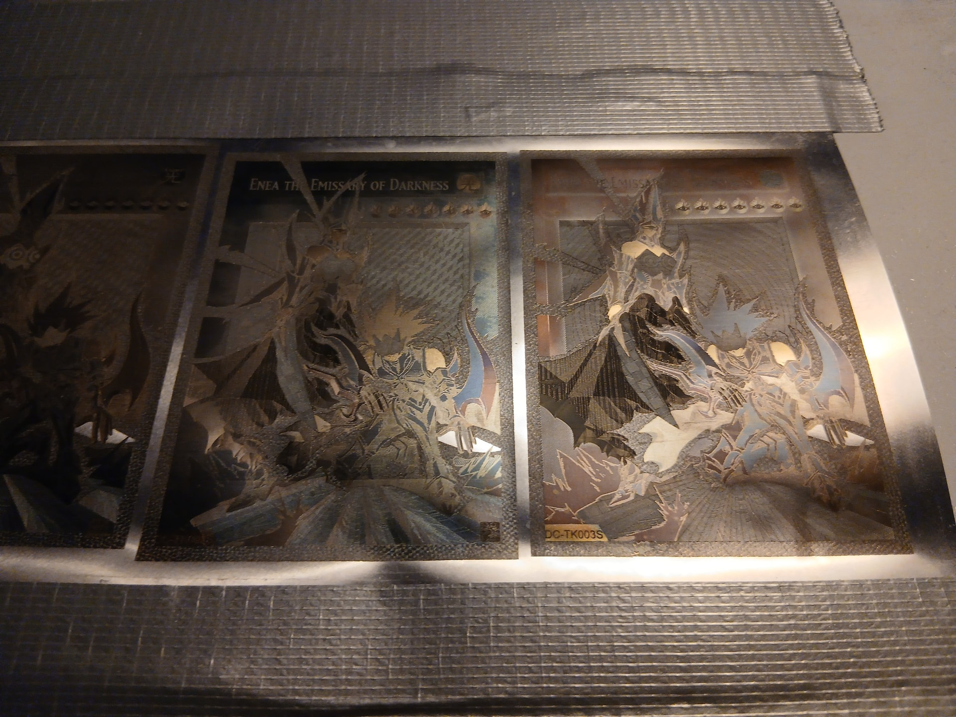
Overall i have done interesting colors but nothing close to a visible-wavelength grating.
Anyone has suggestions ?
Could I ask, is the grating the semicircle marks/ripples within the line (are those spaced at 1micron centre to centre)…or are the gratings the ripples around and between the lines.
At so much less Khz would you expect to see such an effect, and at 40Khz are you getting colour.
The small rings are anywhere between 400-1000 nm, apparently they can be modulated by adjusting fluence and intentionally defocusing the beam (as mentioned in the scientific paper in the video)
They diffract the whole color spectrum in his video. Some of the gratings switched red-green but some (most) went into the deep blue’s too
I was doing some further testing myself with this technique. Since the rings spacing is a function of laser wavelength i am just assuming my 355nm is making gratings that do diffract just not in the visible range. I found literature that has used 355nm and other UV DUV natural harmonics to create such nanostructures with this technique but every single one of them focused more on other aspects. Such as SEM photography, surface tribology, wetness by different fluids and such aspects. None of them focused on the visuals nor had any indication or proof that rainbow diffraction gratings have been achieved with 355nm
That alone made me quite depressed tbh and am maybe considering dipping into a 60W MOPA IR just to test out if it will work. Because the 100W model he uses in the video is decently expensive and in theory i should be able to replicate those exact settings on 60W and just bump the power at 30% or so.
Just scared i won’t get anything for the investment x)
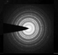
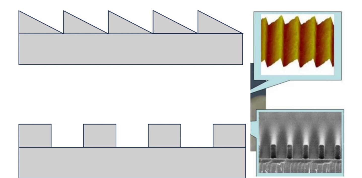
Another idea i had was to take some inspiration from Chip Fabs. I could put a special grating in front of the lens that will make the dot have X nm diffraction rings when it hits the target. Theoretically speaking the ~10micron dot intensity could be spread out in rings like this
And the intense peaks will naturally just ablate material from those points. Then you can adjust the frequency and speed so that each ring lags behind the other one in the spacing you need it to.
Let’s say for example i want a 500nm peak spacing so that is a 1000nm lag which can be done if the freq (Khz) = speed (mm/s) .
I am not sure where to find such a mask gonna ask around the optics lab
Also important, those rings are not ablated from the material. The surface itself is flat as in a later video 8 months later he used an AFM to check if he could mold a holographic sheet out of it. Apparently what happens is that there is this magical point between ablation and melting, where the Steel plasma behaves like a fluid, and the polarized Poynting vector from the incoming laser wave jiggles the surface of the molten fluid which stands under a nanometer layer of Chromium oxide. The layer of molten steel itself is few nanometer thick too. But Cr2O3 has almost double the melting temperature of steel. So it will enclose the thin sheet of molten fluid underneath and transfer the vibration. If the pulse duration, pitch and cooling are at that magical point, the molten steel under the oxide will solidify very fast with the induced vibration mode and permanently form into a grating. The transparent oxide layer coats the grating.
Now theoretically it should be possible to maybe do some solvent chemistry that i am not really proficient at to take the oxide off and make it a moldable Shim but i won’t bother researching into it
P.S : I really wish i had an electron microscope man
Nice video, thanks for posting. I actually bookmarked it to go back to later.
Maybe I’m not understanding what you’re attempting to do, but the video uses a fiber laser to heat the surface. Your profile suggests you use a uv type machine.
UV lasers are termed cold lasers as they work on a photochemical reaction, using virtually no heat. As far as I knew, you need heat to produce any kind of oxide or annealing operation.
To do colors, I thought you needed to heat it up and you’re using uv… So I’m kind of lost to what your trying to do.
I don’t chase down UV applications too much as I don’t have one, however, it seems to me they claim they are good on stainless, usually the best mark is black. That’s about it, not much to go on.
Please enlighten me with a bit more detailed explanation? Such as does it do the same range of colors?
Any chance you could post some photos of your color work for all of us to admire.
That is a myth. UV lasers will absolutely produce hot plasma on steel. And you can get very good colorations too just as you would with an IR laser. In fact you kind of have an advantage on how much heat you can create because they can usually get smaller beam diameters (usually depends on your optics i would not entrust marketing on beam quality)
The cold ablation, i am not sure where that legend started. Even engraving wood with UV is going to smell like burning matches (god knows i wear a respirator mask). In fact the Omni 1 only goes up to 40KHz (1-200ns) which is too long of a pulse duration to get a true clean ablation. That would be possible with MHz fs lasers tho.
As for your other question, i am trying to do diffraction gratings. These colors are the result of growing an oxide layer, whose thickness is going to essentially filter out parts of the white light spectrum. Hence leaving you with your color
A diffraction grating is a nanostructure which has small ridges and bumps on the size order of the wavelength of the light itself. So you are trying to create ridges that are, maybe 500-1000 nanometers.
You can see the issue here, your laser beam diameter is 10+x times that size if you are using good optics.
So the video that i linked shows that you can adjust the laser settings as such that the polarization of the incoming beam will resonate with the semi-liquid molten oxide layer and will make it vibrate before it quickly solidifies (before the next exposure comes few ns later). This makes those small ridges in the picture above and they act as a grating. It will not have 1 constant color, it will shine a spectrum of color depending on the angle you are looking at it from. Like security features
Now i cannot get his exact gratings because (and this is my suspicion) the ring spacing scales with your wavelength. At 355nm i may be generating gratings that are outside the visible spectrum. I tried fixing this by defocusing to increase beam size and had some nice sparkly effects but i only transitioned between yellow - dark purple from 0 - almost 90 degrees of viewing angle. Which is a pathetic color transition.
One idea i had was to actually mod the omni 1, somehow use a beam splitter and re-merge both beams so that the main beam itself holds an interference pattern that i can etch. So the beam is made of few hundred regions of light and dark zones.
This is a WIP from today maybe ill post results some other month
Have I got this correct: The beam creates an area of liquafaction on the medium, The frequency of the beam creates a waveform in the liquid medium equal in depth to the beams applied energy, The medium quickly solidifies leaving a footprint of the frequency in the medium.
Do you think the Oxide layer Thickness is responsible for the range of Spectrum/Colour.
Does the Oxide layer form into both peaks and troughs with no oblation of the metal.
Does the length and contour of the slope from peak to trough + distance to its counter slope, determine the reflected light intensity/brilliance…Where the two reflections combine…from an optimal viewing angle.
Concerning the Masks that you mentioned, Would they create an interference pattern in the beam and where would the blocked energy go.
yes that is correct.
the other 2 questions after that i cannot answer factually but i can give my opinion.
No the oxide layer should not be responsible for the diffraction colors at all, unless you manage to create a thick enough oxide to interfere with the outgoing beam. In fact you are aiming for an oxide as thin and transparent as possible. Ideally few nm of Chromium oxide (depending on what type of stainless you are using). Colors come only from how the incoming wave constructively or destructively interferes with the rest of the color spectrum at an angle.
The shape and slope of the fringes does indeed determine how the final pattern will look. I believe different types of microstructures get different effect. I know for sure straight lines give u a diffraction rainbow, but i am not sure how sinusoidal fringes or crossed fringes would behave. Or even fringes with different shapes.
Like these. These are 2 different rainbow diffraction Gratings from Zokoptics
Zokoptics do a square mask with straight tubular gratings. The beam dimensions could be brought to the mask size or visa-versa by columnation and the result would be a nodal point/standing wave separated by lines of non-displacment. Therfore the point of interest is the mask and it’s ability to create measured areas of non-displacment.
The zokoptics mask uses tubular grates that may cause too much diffraction/diffusion after the bean passes through the mask causing interference of a useful kind…or not!
Does anyone know how the +/-200 areas within the beam are arranged.
I am not sure but i think i am going to commit some funds coming months for some extra equipment and mod the laser into a lithography setup for actual diffraction gratings.
Maybe somehow filter the incoming beam to deliver interference lines (sort of like an interference comb) on steel coated (selectively) in antireflective coating and photopolymer. Electroplate the metal, remove the polymer and could theoretically have much higher fidelity gratings than the video by Applied Science.
Tho the issues here are a few too many.
Antireflective coating to stop standing waves , at only few nm thick is best done by Magnetron Sputtering so that is a machine i have always wanted an excuse to get.
I am not sure how to approach the optics tho. Galvos here make life hard. I would have to split the beam and make them interfere. Adding the galvo motion into account and it is a nightmare. Probably flat bed with constant overhead beam would be best. 50 micron beam with 800-1000 nm fringes inside. Get rid of the F-Theta lens for a square beam shaper but how to create the fringes in the beam tho? If i have a 50 micron beam even a 3D printer bed with good bearings could give decent positional accuracy. But the overall optical resolution of the hologram would be limited by it. If i wanted a sub pixel smaller than 50 would probably dip into air bearings.
Ah, I was theorising more along the lines of cymatic resonance and the grated mask lense creating the gap from peak to peak so the number of troughs equals the number of gratings (traveling on the x axis and scanning as usual). Was also thinking the fringes would occur by resonance according to pulse/freq.
I see your point about the beam splitter and am wondering if the beam Must be absolutely perpendicular to the material on exiting the optics when tuning is dependent on the angle of interference.
Also, oxide layers are apparently controllable up to ~100nm. And circular patterns can be more effective than I had thought.