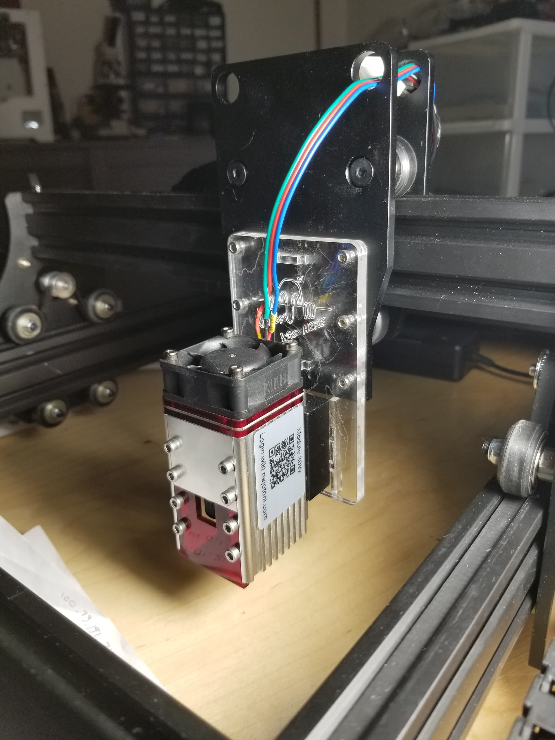
I have hooked up a Neje 3 Max diode (A40640) to A chinese control board that came with the diode laser setup I already had. Motors work fine, but the TTL / PWM will not fire the laser. I have the PWM hooked up to FAN on the control board, just like it was on the previous diode.
The previous diode I had was a Universal Blue Laser Engraver.
I’m at a loss for what to try. I get the following from console when I type in $$
$0=10
$1=250
$2=0
$3=0
$4=0
$5=0
$6=0
$10=1
$11=1.000
$12=0.002
$13=1
$20=0
$21=0
$22=0
$23=7
$24=25.000
$25=500.000
$26=250
$27=2.000
$30=1000
$31=0
$32=1
$100=80.000
$101=80.000
$102=800.000
$110=1000.000
$111=1000.000
$112=1000.000
$120=400.000
$121=400.000
$122=200.000
$130=200.000
$131=200.000
$132=200.000
No idea is crazy. I’ll try it. I really need this to work.
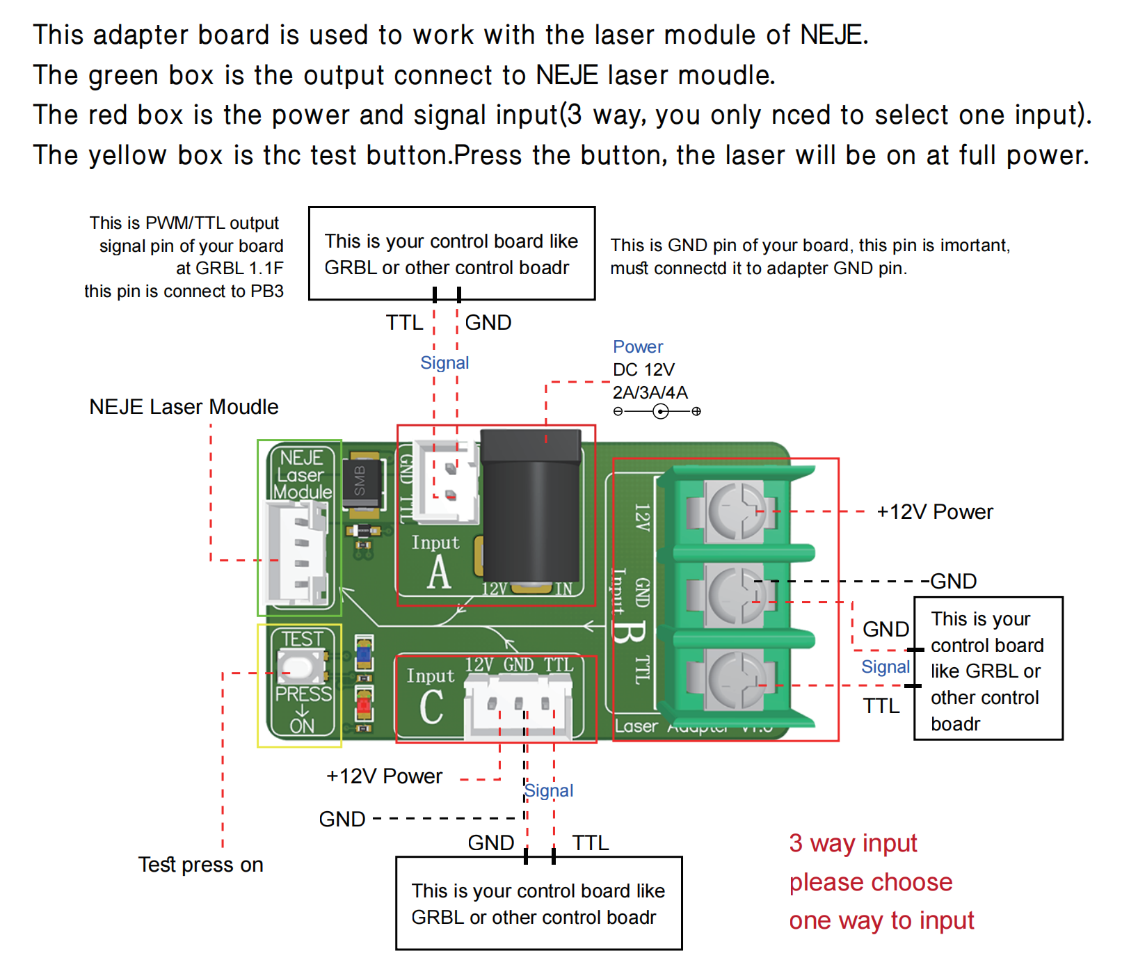
Neje module laser came with a separate little pcb from which start a 4 wire cabling to the laser module and in which you have to connect power at 12V and the pwm signal.
post a photo of your cabling please.
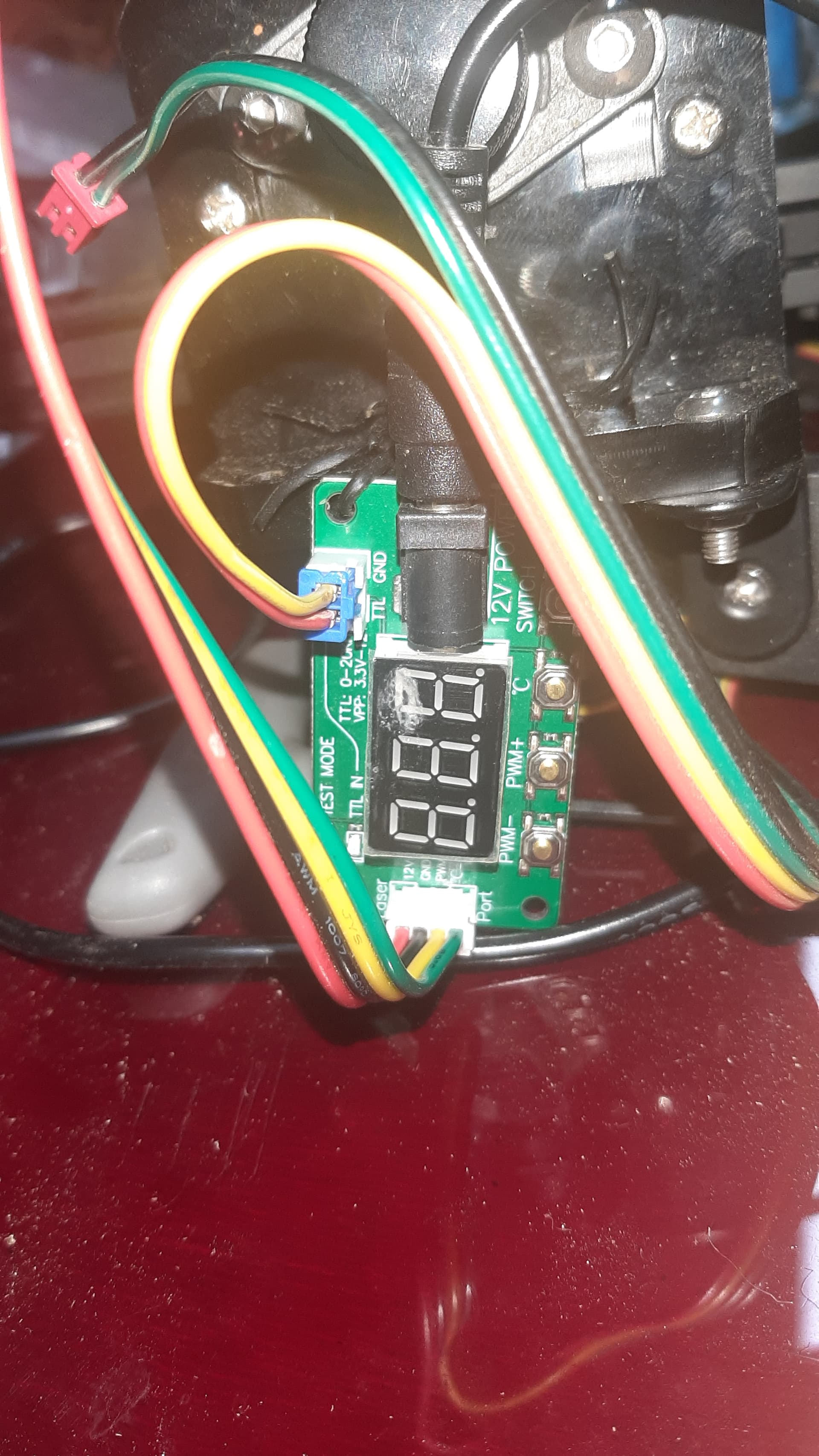
I can’t take a picture right now but these are 2 boards that Neje send. One has an LED read out of laser power. The other is bodhi. I’m going that board up to TTL. It’s the same as an PWM. I’ve tried both boards. When I had it all hooked up to an Arduino I could get the laser to turn on with the fire button but not this original controller. This original controller will fire the original diode. I’m confused
It would help to know what kind of laser was on the machine before you upgraded and what the available controls were. Some of these do not supply power to the module, but turn it on via the pwm, which supplies the current.
Higher wattage lasers usually require a separate supply.
You will need three basic connections, power, ground and the pwm control. It sounds like the laser module is working, but you are not wired up correctly. What happens many times, is you think you know how it works … but find it’s not quite the truth…
Let us know what you are upgrading from and any connection between the two lasers… need some way to identify which pin is what…
Many lasers have a different focal length … that is why mine is lower… keep in mind when mounting.
I have it hooked up like it should be in the picture you shared.
The prior laser name is Blue Universal Engraver diode.
The controller uses the FAN as PWM and ground is hooked up to ground and on the smaller, laser control board the FAN cable goes to the TTL on Input A. I have 12V hooked up directly to the laser board, a different 12V hooked up to the control board that runs the steppers.
I guess this afternoon I should get my multimeter out and check the volts on the FAN pin when I hit FIRE in lightburn. That will help me determine if it’s sending any power. Is it is sending power then I’ll know the issue is somewhere closer to the laser.
What controller is this on? If you can confirm that the board is generating proper voltages on the FAN PWM then it’s possible that the supported frequency of the laser module doesn’t support whatever is being sent from the controller. These modules can typically take a wide range so would be surprised if this is the case.
I can’t find any good literature about the Neje module. This site indicates that 1Khz is recommended but doesn’t list a range. I believe that matches GRBL default.
However, FAN controls are sometimes quite slow… sub 100 Hz range are common. Not sure if this is a factor here.
Does the original laser still work with the controller?
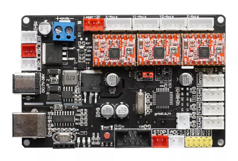
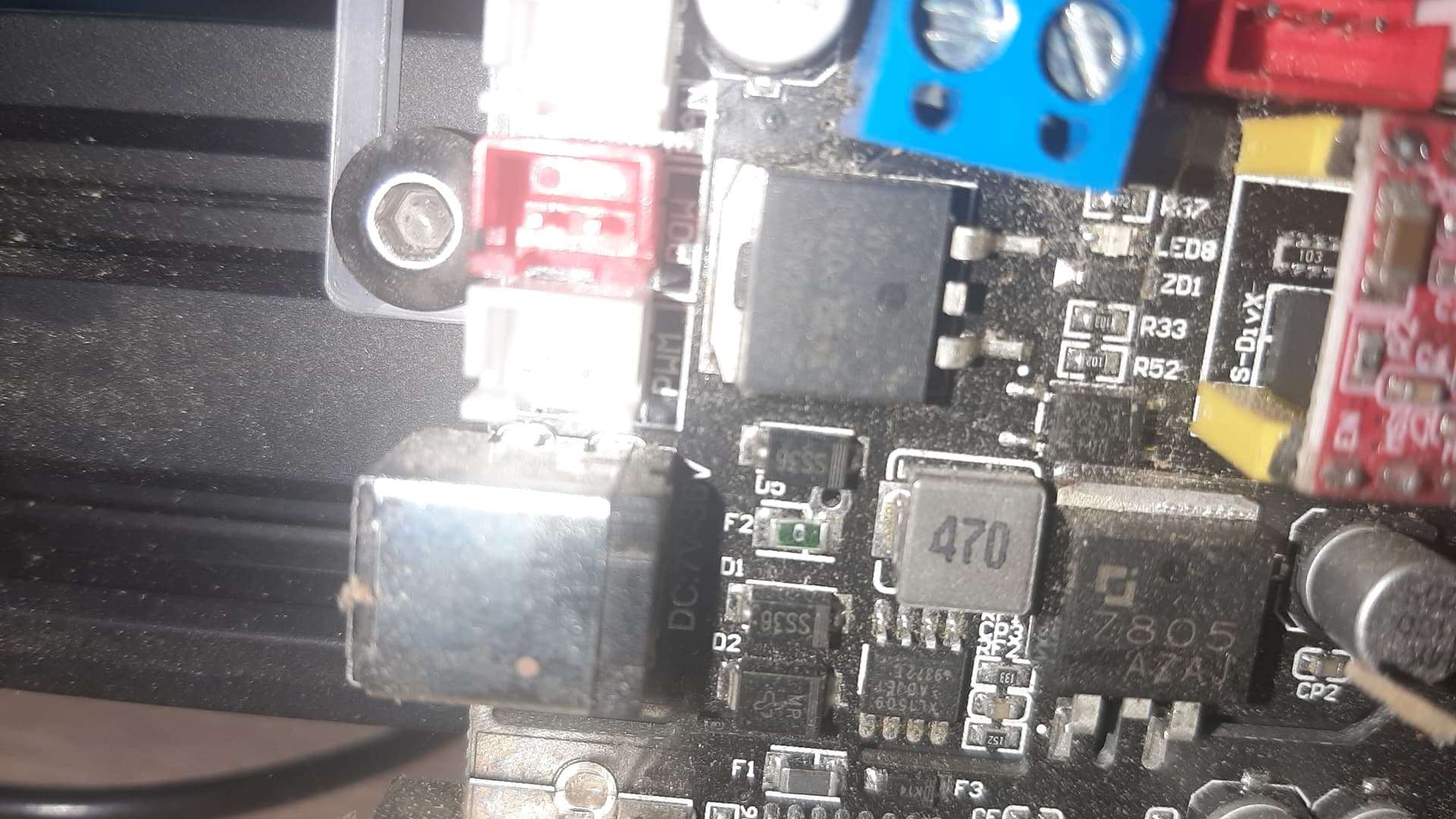
This is a picture of the control board being used. And I just realized that on the top left where you see White, red, white connectors, they are, from top to bottom, FAN, POW (power), and…PWM. LOL. It used the FAN hookup on the diode I replaced, but I’m about to go out to the shop and hook up the PWM. I won’t be surprised if the laser turns on just fine.
Plugging the TTL cable into the PWM on the board did not work. I plugged the old diode laser back in with it’s control board and was able to use the POW and PWM outputs to control that laser’s on / off function with the Fire button in Lightburn. So LB is definitely sending a signal but the NEJE A40640 isn’t interpreting it correctly. Or not even seeing it if the frequency of the signal is different.
In the past, I was did have an Arduino with CNC Shield v3 hooked up and was able to use that to get the A40640 to fire in lightburn, but couldn’t get the steppers to run correctly. I’m so frustrated.
It’s somewhat common but only for boards meant for 3d printers being repurposed. It’s not common for dedicated laser or CNC systems.
Can you take a photo of how you’ve connected the controller to the laser module? Are you using the Neje adapter board?
Basically for the Neje, all it should need to see on the PWM pin is a voltage higher than 2.5V to activate the laser. It shouldn’t take much. It’s up to 12 V tolerant apparently so even putting up to 12V on the PWM should make it fire without issue.
Yes, I’m using the controller (Neje supplies 2 different types) for Neje.
The main control board (with the A4988) is the Chinese board that came with the Universal Engraver 15,000mW.
So I have 2 options. First would be to use the original control board and somehow get the PWM to work with the Neje diode. This one runs the stepper motors just fine.
The second option, is to use an Arduino Uno with CNC Shield and DRV8825 chips. I hooked this up tonight just to see if starting from scratch would help and nothing. No movement of the steppers, no turning on and off of the laser. I have the PWM on the CNC Shield hooked up to the +Z pins which is what the Arduino uses as the PWM (pin 11 on the Arduino).
The image I posted earlier of an identical control board is better.
The yellow/red 2-pin wire plugs into the white PWM on the main board, left side just under the red POW connector. Then, the stepper motor wires are plugged into the top of the board above the A4988 chips. I power it with a 12V 4A-5A power supply. It’s truly very simple, yet something is happening to the PWM signal. The PWM signal works on the old diode. Tested that again tonight, so I believe the signal is being lost or not interpreted correctly by the Neje board.
You’re saying it was constantly at 5V? Can you setup a design with 3 objects all in their own layer? Layer 1 is 0% power, layer 2 is 50% power, and layer 3 100% power.
While running each layer test voltage.
If you’re getting a constant 5V 2 things is true:
your controller is not working correctly
your laser module should be firing constantly
So something isn’t adding up so the key will be sorting out where and why.
I’m looking at the wiring photos. A few questions:
if you pushing the test button on the neje adapter board, does the laser fire?
are the pins on the controller side labeled? It’s unclear from the photos which is ground and which is PWM. It’s clear on the adapter board
Can you run $I in Console and confirm your GRBL version?